
Intelligent Real-Time Controllers Operating Instructions and Specifications

cFP-2200/2210/2220 12 ni.com
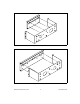
2. Bolt the rack-mount bracket to a standard 19 in. rack.
3. Connect the PE ground terminal on the cFP-BP-x to safety ground.
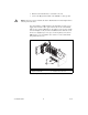
Caution Disconnect power and make sure that no I/O modules are in the backplane before
removing it from the rack.
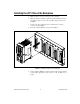
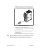
You can install an 8 in. DIN rail in the rack-mount kit to mount a power
supply such as the PS-5. The captive #10-32 nuts on the rack-mount kit
make it easy to attach a DIN rail. Use two #10-32 screws of 3/8 in. length
as shown in Figure 18. If you want to install flat washers under the screw
heads, use a slightly longer screw, up to 1/2 in. length. If you need more
DIN rail space, you can install an 18 in. rail in a second rack-mount kit
using four #10-32 screws.
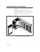
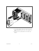
Figure 18. Installing an 8 in. DIN Rail in the Rack-Mount Kit
1 cFP-BP-4 Backplane
2 Captive #10-32 Nuts
3 8 in. DIN Rail
4 #10-32 Screws, 3/8–1/2 in.
1
2
3
4