
Intelligent Real-Time Controllers Operating Instructions and Specifications


cFP-2200/2210/2220 2 ni.com
This document describes how to mount the cFP-2200/2210/2220
controllers, how to connect the controllers to networks, and how to use
the features of the controllers. This document also contains specifications
for the controllers. In this document, the cFP-2200/2210/2220 controllers
are referred to inclusively as the cFP-22xx.
What You Need to Install the cFP-22xx
❑ cFP-22xx intelligent real-time controller
❑ cFP-BP-4 or cFP-BP-8 Compact FieldPoint backplane
❑ Compact FieldPoint I/O modules
❑ Compact FieldPoint connector blocks and/or cables
❑ Ethernet cable
❑ Mounting hardware (DIN rail, panel-mount, or rack-mount accessory)
❑ Two M4 or number 10 panhead screws (for panel mounting only)
❑ Number 2 Phillips screwdriver
❑ 14 AWG (1.6 mm) wire with ring lug to fit #8 screw
❑ 11–30 VDC Power supply
❑ PC running Windows
❑ FieldPoint software 6.0.1 or later
❑ LabVIEW Real-Time Module 8.5.1 or later
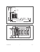
Mounting the Compact FieldPoint Backplane
You can mount the cFP-BP-x backplane on a 35 mm DIN rail, on a panel,
or in a standard 19 in. rack. NI recommends DIN rail mounting for the
cFP-BP-4 only. Use panel mounting or rack mounting for the cFP-BP-8.
Use the panel mounting method for high shock and vibration applications.
Before using any mounting method, record the serial number from the back
of the backplane. You will be unable to read the serial number after you
have mounted the backplane.
Each set of mounting instructions in this document includes an instruction
to connect the protective earth (PE) ground terminal on the cFP-BP-x
backplane to the system safety ground. The backplane PE ground terminal