
Intelligent Real-Time Controllers Operating Instructions and Specifications


© National Instruments Corporation 23 cFP-2200/2210/2220
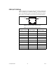
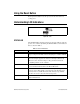
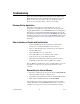
Figure 27 shows how to wire several FP-1001 banks in an RS-485 network
controlled by the cFP-2220. Only two FP-1001 banks are shown, but the
cFP-2220 can control up to 24 FP-1001 banks. Install 120 Ω termination
resistors at each end of the network as shown in Figure 27.
Figure 27. Wiring for an RS-485 Network Controlled by the cFP-2220
COM 4 is designed to operate in four-wire mode as shown in Figure 27.
You can use COM 4 in two-wire mode, but you must design your
application so that it filters out the writes that echo back over the read
channels. NI does not recommend this method.
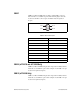
NI offers a DIN rail–mountable screw terminal adapter that you can use
to connect termination resistors to COM 4. The adapter is part number
778674-01.
Cable adapters for the 10-position modular jacks are available from NI.
Part numbers 182845-01, -02, and -03 are 1, 2, and 3 m cable adapters for
connecting the 10-position modular jack to a 9-position D-SUB plug.
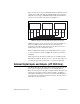
External Digital Inputs and Outputs (cFP 2220 Only)
The cFP-2220 has two digital inputs and two digital outputs that you can
use to connect a simple operator interface to the controller. Refer to
Figure 1 for the location of the input and output terminals. The inputs and
outputs appear in software as Input 1, Input 2, Output 1, and Output 2.
Logic high for the DIO ports is +5 V. Logic low is 0 V. The DIO ports are
not isolated and are not intended for field connections. Use them only for
simple VI controls and indicators.
RXD– RXD+ TXD– TXD+
RX–
RX+ TX– TX+ RX– RX+ TX– TX+
cFP-2220 COM 4 FP-1001 FP-1001
120 Ω 120 Ω120 Ω120 Ω