FieldPoint™ FP-1000 and FP-1001 RS-232/RS-485 Network Module User Manual FieldPoint FP-1000/FP-1001 User Manual July 1997 Edition Part Number 321631A-01 © Copyright 1997 National Instruments Corporation. All rights reserved.
Internet Support support@natinst.com E-mail: info@natinst.com FTP Site: ftp.natinst.com Web Address: http://www.natinst.com Bulletin Board Support BBS United States: (512) 794-5422 BBS United Kingdom: 01635 551422 BBS France: 01 48 65 15 59 Fax-on-Demand Support (512) 418-1111 Telephone Support (U.S.
Important Information Warranty The FieldPoint modules are warranted against defects in materials and workmanship for a period of one year from the date of shipment, as evidenced by receipts or other documentation. National Instruments will, at its option, repair or replace equipment that proves to be defective during the warranty period. This warranty includes parts and labor.
Table of Contents About This Manual How to Use This Manual Set ........................................................................................ ix Organization of This Manual ........................................................................................ x Conventions Used in This Manual................................................................................ x Related Documentation.................................................................................................
Table of Contents SnapShot Feature.......................................................................................................... 3-2 Programmable Power-Up State .................................................................................... 3-3 HotPnP (Hot Plug and Play)......................................................................................... 3-4 HotPnP During Power-Up .............................................................................
Table of Contents Figure 2-8. RS-485 Connector Pinout for the FP-1000 and FP-1001 ...................... 2-7 Figure 2-9. Terminating RS-485 Using the Combicon Adapter .............................. 2-8 Figure 2-10. Typical Signal Connections for Host Computer Connected to One FP-1000 and Multiple FP-1001 Network Modules........................ 2-8 Figure 2-11. Typical Signal Connections for Host Computer Connected to Multiple FP-1001 Network Modules.....................................................
About This Manual This manual describes how to install and use the FieldPoint FP-1000 and FP-1001 network modules.
About This Manual Organization of This Manual This manual is organized as follows: • Chapter 1, FP-1000 and FP-1001 Network Module Overview, provides an overview of the FieldPoint network modules. • Chapter 2, Installation and Configuration, describes how to install and configure your FieldPoint network module, connect it to an RS-232 or RS-485 network, and connect power to the network module. • Chapter 3, Feature Set Description, describes the feature set for the FP-1000 and FP-1001 network modules.
About This Manual italic Italic text denotes emphasis, a cross reference, or an introduction to a key concept. This font also denotes text from which you supply the appropriate word or value, as in Windows 3.x. italic monospace Italic text in this font denotes that you must supply the appropriate words or values in the place of these items. monospace Text in this font denotes text or characters that should literally enter from the keyboard, sections of code, programming examples, and syntax examples.
FP-1000 and FP-1001 Network Module Overview Chapter 1 This chapter provides an overview of the FieldPoint network modules. The FP-1000 FieldPoint network module connects an industrial RS-232 network to FieldPoint I/O modules. The FP-1001 FieldPoint network module connects an industrial RS-485 network to FieldPoint I/O modules. The FP-1000 and FP-1001 support standard commands (subset of Optomux command set), and a set of extended commands to completely support the FieldPoint I/O modules.
Chapter 1 FP-1000 and FP-1001 Network Module Overview FP-1001 Connects to RS-485 The FP-1001 FieldPoint network module connects directly to an RS-485 adapter card that is installed in your host computer. Since RS-485 is inherently a multidrop network, the FP-1001 does not provide a separate RS-485 repeater. You can network multiple FP-1001 modules in multidrop fashion. The FP-1001 communicates over RS-485, utilizing full-duplex mode.
Chapter Installation and Configuration 2 This chapter describes how to install and configure your FieldPoint network module, connect it to an RS-232 or RS-485 network, and connect power to the network module. Installing the Network Module The FieldPoint network modules have rugged, simple clips for mounting reliably onto a standard 35 mm DIN rail. Follow these steps to mount the network module onto a DIN rail. Terminal bases must be connected to the network module before power is applied. 1.
Chapter 2 Installation and Configuration 3. Slide the network module to the desired position on the DIN rail. After the module is in position, push the rail snap into the locked position to lock the module in place on the DIN rail, as shown in Figure 2-3. Network Module DIN Rail Rail Snap Unlocked (Position Module Along DIN Rail) Rail Snap Locked Figure 2-3.
Chapter 2 Installation and Configuration 3. Attach the terminal base to the network module by firmly mating the local bus connectors. 4. To add more terminal bases, install them on the rail and mate their local bus connectors together. 5. Place the protective cover that you removed from the network module on the last terminal base on the bank, as shown in Figure 2-4. Local Bus Connectors Firmly Mated Protective Cover Rail Snap Locked DIN Rail Figure 2-4.
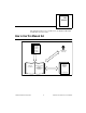
Chapter 2 Installation and Configuration Host Computer FP-1001 FP-1001 FP-1000 RS-485 RS-232 Figure 2-5. Host Computer Connected to One FP-1000 and Two FP-1001 Network Modules Connecting the FP-1001 to the Network This section describes the network configurations possible with the FP-1001 FieldPoint network module. The connector pinouts are described in the RS-485 Interface Specifications section later in this chapter.
Chapter 2 Installation and Configuration Host Computer with RS-485 Board Installed FP-1001 FP-1001 FP-1001 RS-485 Figure 2-6. Host Computer Connected to Three FP-1001 Network Modules The multidrop topology used in the networking configurations provides protection against power failures at individual FieldPoint banks. It eliminates the possibility that a power failure at one FP-1001 bank might affect the communication between other banks in your network.
Chapter 2 Installation and Configuration Both serial interfaces are self-configured to use the following parameters: 1 Start Bit, 8 Data Bits, 1 Stop Bit, No Parity The supported baud rates are 300, 1200, 2400, 9600, 19200, 38400, 57600, and 115200. Refer to the Configuring the Network Module section for information about setting the baud rate for your modules.
Chapter 2 Installation and Configuration The FP-1000 does not use RS-232 hardware handshaking, but it still asserts the RTS and DSR signals for host computers or software that may require these signals. A host computer that does not use these signals does not need to connect to them.
Installation and Configuration + RX X R D GN X T + TX Chapter 2 RS-485 + Signal Pair – + RS-485 – Signal Pair 120 Ω 120 Ω Figure 2-9. Terminating RS-485 Using the Combicon Adapter An RS-485 network also needs biasing resistors to protect the devices on the network against noise during intervals when no RS-485 drivers are transmitting on the network. The host computer’s RS-485 interface normally has provision for such biasing resistors.
Chapter 2 FP-1001 RX FP-1001 FP-1001 TX RX Installation and Configuration TX RX 120Ω + TX To Host Computer's RS-485 – Receive Input Pair (RX) 120Ω – 120Ω From Host Computer's RS-485 + Transmit Output Pair (TX) 120Ω Connect the TX outputs of the host computer to the RX inputs of the FP-1001, and the RX inputs of the host computer to the TX outputs of the FP-1001. Figure 2-11.
Chapter 2 Installation and Configuration Follow these steps to set the address and baud rate for your network module. 1. Choose and set a network address. Refer to the following section, Setting the Network Address, for more information. 2. Choose and set the baud rate. For more information, refer to the section, Setting the Baud Rate, later in this chapter. 3. Write your address and baud rate settings in the space provided on the network module label. 4.
Chapter 2 Installation and Configuration Table 2-1.
Chapter 2 Installation and Configuration Setting the Baud Rate Switches 6-8 set the network module baud rate. Table 2-2 shows the switch positions and the corresponding network baud rates of the network module. Note: If you are connecting more than one network module to the same host computer port, ensure that every network module’s baud rate setting is identical. Table 2-2.
Chapter 2 Installation and Configuration V V 11-30 VDC + - C C V To Adjacent Terminal Base (Optional Connection) C Figure 2-13. FP-1000 and FP-1001 Power Connector Pinout The two terminals labeled V are internally connected on the network module, as are the two terminals labeled C. Power must be applied to one V and C pair for operation of the FieldPoint bank.
Chapter 3 Feature Set Description This chapter describes the feature set for the FP-1000 and FP-1001 network modules. Both the FP-1000 and FP-1001 have an identical feature set, so this chapter uses the term network module to refer to either one. Any specific differences are noted. High-Speed Local Bus The network modules provide a high-speed local bus for communication to the I/O modules in the bank.
Chapter 3 Feature Set Description Note: • Watchdog enabled/disabled status for each I/O module. • Watchdog timeout value for the bank. Each bank has only one watchdog timeout value that is common for all the modules in that bank. In addition, the current watchdog timeout value is not stored when you store the SnapShot. SnapShot Feature Many applications require that, upon startup, the system’s I/O power up with user-specified configuration and output levels rather than factory default settings.
Chapter 3 Feature Set Description If you have enabled the SnapShot feature, the network module restores the stored settings to all I/O modules and channels in the bank every time you power up, until you disable the SnapShot feature. If the SnapShot feature is disabled, the FieldPoint bank will power up with factory-default settings. At some time you might want to change the stored SnapShot information.
Chapter 3 Feature Set Description • Attribute and range settings of each channel. • Output values of each channel. • Watchdog data value of each channel. See the Network Watchdog Timer section in this chapter for more information. • Watchdog data enabled (or disabled) status for each channel. See the Network Watchdog Timer section in this chapter for more information. • Watchdog timer enabled (or disabled) status of each module.
Chapter 3 Feature Set Description HotPnP During Power-Up Upon power-up, the network module automatically uploads an electronic data sheet (EDS) from each I/O module in its bank. The network module then configures each I/O module in the bank to factory default settings in the module’s EDS, or stored SnapShot settings if the SnapShot feature is enabled.
Chapter 3 Feature Set Description If the replacement module is incompatible with the one that was removed, the network module looks at the information stored in the SnapShot. If the SnapShot is enabled and the replacement module is compatible with the information in the SnapShot, the network module configures the replacement module with the SnapShot configuration. Otherwise, the network module configures the replacement module to factory default settings.
Chapter 3 Feature Set Description Power-On Self Test (POST) The power-on self test (POST) is a test suite that the network module performs at power up to verify its own operational status. The test is non-invasive and therefore does not affect the operation of the network, nor does it affect any of your field wiring connected to the terminal bases in the bank.
Chapter 3 Feature Set Description The yellow NETWORK LED is lit during transmissions from the host computer on the network. This LED indicates that the network module is receiving from the network, and that the communication wires to it are not broken. The NETWORK LED gets brighter as activity on the network increases. The yellow ACCESS LED flashes when the network module or any of the I/O modules in its bank respond to the host computer.
Using the FieldPoint Software Chapter 4 This chapter describes how to use the FieldPoint hardware with various servers and software packages. FieldPoint Software Overview Your FieldPoint software consists of three parts: the FieldPoint Explorer, the FieldPoint Server, and a FieldPoint driver for Lookout. The FieldPoint Explorer and the FieldPoint Server are both 32-bit applications that run on Windows 95 or Windows NT. • The FieldPoint Explorer is a configuration utility for FieldPoint modules.
Chapter 4 Using the FieldPoint Software Using the FieldPoint Explorer You can use the FieldPoint Explorer to accomplish the following tasks: • Configure the characteristics and hardware of a FieldPoint device network • Configure the tag name space and I/O items of the FieldPoint Server • Write and read I/O values to and from the FieldPoint hardware After configuring the FieldPoint system with FieldPoint Explorer, you can save the configuration in an Industrial Automation Kernel (IAK) file (.
Chapter 4 Using the FieldPoint Software Using the FieldPoint Server with LabVIEW To use the FieldPoint server from LabVIEW, first configure and test your FieldPoint device network from FieldPoint Explorer. After you are satisfied with the configuration, save your .iak configuration file. You can then access named FieldPoint item values using the LabVIEW FieldPoint Server Interface.
Chapter 4 Using the FieldPoint Software Using the FieldPoint Lookout Driver The FieldPoint Lookout driver uses the configuration information in the IAK file created by the FieldPoint Explorer for its own configuration. The tag names used with the FieldPoint Lookout driver are the same as the names assigned using FieldPoint Explorer. There is a separate disk in your kit that contains the FieldPoint Lookout driver. This disk also contains documentation for this driver in the lkreadme.wri file.
Appendix A Specifications This appendix describes the specifications of the FP-1000 and FP-1001 network modules. All FieldPoint network modules undergo extensive testing for operating under rugged environmental conditions that exist in industrial applications. FieldPoint network modules are designed and tested for immunity and susceptibility, as well as for emissions. Network FP-1000 ..............................................1 RS-232 port, 1 RS-485 repeater port FP-1001 .............................
Appendix A Specifications RS-485 Isolation ................................ 2500 Vrms breakdown, 250 Vrms operational Environment Operating Temperature....................... –40° C to +70° C Storage Temperature .......................... –55° C to + 100° C Relative Humidity .............................. 5% to 90% noncondensing Compliance Electrical Safety ................................. designed to meet IEC 1010 EMI Emissions/Immunity...................
Appendix Customer Communication B For your convenience, this appendix contains forms to help you gather the information necessary to help us solve your technical problems and a form you can use to comment on the product documentation. When you contact us, we need the information on the Technical Support Form and the configuration form, if your manual contains one, about your system configuration to answer your questions as quickly as possible.
Fax-on-Demand Support Fax-on-Demand is a 24-hour information retrieval system containing a library of documents on a wide range of technical information. You can access Fax-on-Demand from a touch-tone telephone at (512) 418-1111. E-Mail Support (currently U.S. only) You can submit technical support questions to the applications engineering team through e-mail at the Internet address listed below. Remember to include your name, address, and phone number so we can contact you with solutions and suggestions.
FieldPoint System Configuration Form Record the settings and revisions of your hardware and software on the line to the right of each item. Complete a new copy of this form each time you revise your software or hardware configuration, and use this form as a reference for your current configuration. Completing this form accurately also helps us to answer your questions more efficiently.
FieldPoint Banks Please use one page per FieldPoint bank.
Technical Support Form Photocopy this form and update it each time you make changes to your software or hardware, and use the completed copy of this form as a reference for your current configuration. Completing this form accurately before contacting National Instruments for technical support helps our applications engineers answer your questions more efficiently.
Documentation Comment Form National Instruments encourages you to comment on the documentation supplied with our products. This information helps us provide quality products to meet your needs. Title: FieldPoint™ FP-1000 and FP-1001 RS-232/RS-485 Network Module User Manual Edition Date: July 1997 Part Number: 321631A-01 Please comment on the completeness, clarity, and organization of the manual.
Glossary Prefix Meanings Value m- milli- 10–3 k- kilo- 103 M- mega- 106 % percent ° degrees 0x precedes a hexadecimal number Ω ohms B bytes bank The combination of one FieldPoint network module and one or more terminal bases and I/O modules.
Glossary I/O input/output IEC International Electrotechnical Commission in.
Index A serial port connections, 2-5 to 2-9 isolation of RS-485 interface (note), 2-5 to 2-6 RS-232 interface specifications, 2-6 to 2-7 RS-485 interface specifications, 2-7 to 2-9 terminal base connection, 2-2 to 2-3 connector pinouts power connector (figure), 2-13 RS-232 ports (figure), 2-6 RS-485 ports (figure), 2-7 customer communication, B-1 to B-2, xi ACCESS LED, 3-7 addresses, setting address and baud rate, 2-9 to 2-10 network address, 2-10 to 2-11 unique address for each module (note), 2-10 B ba
Index F H fax and telephone support, B-2 fax-on-demand support, B-2 feature set description, 3-1 to 3-8 high-speed local bus, 3-1 HotPnP (Hot Plug and Play), 3-4 to 3-6 LED indicators, 3-7 to 3-8 network watchdog timer, 3-1 to 3-2 power-on self test (POST), 3-6 to 3-7 Programmable Power-Up State, 3-3 to 3-4 SnapShot feature, 3-2 to 3-3 FieldPoint banks calculating power for bank, 2-13 maximum number of banks, 1-1 network watchdog timer, 3-1 to 3-2 SnapShot feature, 3-2 to 3-3 FieldPoint network modules.
Index L R LabVIEW software, using with FieldPoint Server, 4-3 LabWindows/CVI software, using with FieldPoint Server, 4-3 LED indicators, 3-7 to 3-8 local bus, high-speed, 3-1 removing FieldPoint network module, 2-2 RS-232 ports connector pinout (figure), 2-6 FP-1000 connection to, 1-1 interface specifications, 2-6 to 2-7 self-configuration parameters, 2-6 RS-485 ports Combicon adapter for termination (figure), 2-8 connector pinout (figure), 2-7 FP-1001 connection to, 1-2 interface specifications, 2-7 to
Index T technical support, B-1 to B-2 telephone and fax support, B-2 terminal base connection, 2-2 to 2-3 termination and biasing, RS-485 ports, 2-7 to 2-9 W watchdog timer, 3-1 to 3-2 FieldPoint FP-1000/FP-1001 User Manual I-4 © National Instruments Corporation