
User Manual Network Module FP-1000, FP-1001

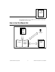
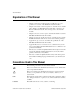

Table of Contents
FieldPoint FP-1000/FP-1001 User Manual vi
©
National Instruments Corporation
SnapShot Feature.......................................................................................................... 3-2
Programmable Power-Up State .................................................................................... 3-3
HotPnP (Hot Plug and Play)......................................................................................... 3-4
HotPnP During Power-Up ............................................................................. 3-4
HotPnP During Operation.............................................................................. 3-5
Inserting New I/O Modules ............................................................. 3-5
Replacing I/O Modules.................................................................... 3-5
Power-On Self Test (POST)......................................................................................... 3-6
LED Indicators ............................................................................................................. 3-7
Chapter 4
Using the FieldPoint Software
FieldPoint Software Overview ..................................................................................... 4-1
Using the FieldPoint Explorer...................................................................................... 4-2
Using the FieldPoint Server with BridgeVIEW........................................................... 4-2
Using the FieldPoint Server with LabVIEW................................................................ 4-3
Using the FieldPoint Server with LabWindows/CVI................................................... 4-3
Using the FieldPoint Lookout Driver........................................................................... 4-4
Using FieldPoint with Optomux Servers...................................................................... 4-4
Appendix A
Specifications
Appendix B
Customer Communication
Glossary
Index
Figures
Figure 2-1. DIN Rail Clip in the Unlocked Position................................................ 2-1
Figure 2-2. Installing the Network Module onto a DIN Rail................................... 2-1
Figure 2-3. Locking the FieldPoint Network Module onto a DIN Rail................... 2-2
Figure 2-4. Connecting Terminal Bases................................................................... 2-3
Figure 2-5. Host Computer Connected to One FP-1000 and Two FP-1001
Network Modules.................................................................................. 2-4
Figure 2-6. Host Computer Connected to Three FP-1001 Network Modules ......... 2-5
Figure 2-7. RS-232 Connector Pinout for the FP-1000 ........................................... 2-6