
Isolated Analog Input Modules User Guide

© National Instruments Corporation 5 SCC-AI Series Isolated Analog Input Modules
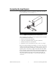
Connecting the Input Signals
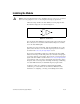
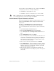
The SCC-AIXX has a fixed screw-terminal receptacle and a removable
screw-terminal block, as shown in Figure 1-2.
Figure 1-2. SCC-AIXX Two-Part Screw-Terminal System
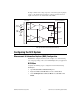
After you install the SCC-AIXX, connect the input signals to the removable
screw-terminal block of the module.
1. Remove power from the signal lines.
2. Strip 7 mm of insulation from the ends of the signal wires.
3. Insert the wires into the screw terminals.
4. Tighten the screws to 0.5 to 0.6 N · m (4.4 to 5.3 lb - in.) of torque.
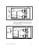
Each screw terminal is labeled by pin number <1..4>. Pins 1 and 2 form a
channel routed to E Series DAQ device channel X+8, and pins 3 and 4 form
a channel routed to the E Series DAQ device channel X, where X is 0 to 7
depending on the socket where you plug in the module. The SCC-AIXX
provides channel-to-ground and module-to-module isolation only. It does
not provide isolation between the two channels of the SCC-AIXX. Because
both channels must have the same reference voltage, pins 1 and 3 are
connected together internally. Figure 1-3 shows the SCC-AIXX signal
connections.
1 SCC Screw-Terminal Receptacle 2 Removable Screw-Terminal Block
3
2
1
4
1
2