CBIHWum.
CBIHWum.book Page 2 Thursday, October 29, 1998 1:56 PM Internet Support E-mail: support@natinst.com FTP Site: ftp.natinst.com Web Address: http://www.natinst.
CBIHWum.book Page 3 Thursday, October 29, 1998 1:56 PM Important Information Warranty The NI 5911 is warranted against defects in materials and workmanship for a period of one year from the date of shipment, as evidenced by receipts or other documentation. National Instruments will, at its option, repair or replace equipment that proves to be defective during the warranty period. This warranty includes parts and labor.
CBIHWum.book Page iv Thursday, October 29, 1998 1:56 PM Conventions The following conventions are used in this manual: » The » symbol leads you through nested menu items and dialog box options to a final action. The sequence File»Page Setup»Options»Substitute Fonts directs you to pull down the File menu, select the Page Setup item, select Options, and finally select the Substitute Fonts options from the last dialog box.
CBIHWum.book Page v Thursday, October 29, 1998 1:56 PM Contents Chapter 1 Taking Measurements with the NI 5911 Connecting Signals ........................................................................................................1-1 Introduction to the VirtualBench-Scope Soft Front Panel.............................................1-2 Soft Front Panel Features ................................................................................1-3 Using the VirtualBench-SCOPE Soft Front Panel .............
CBIHWum.book Page vi Thursday, October 29, 1998 1:56 PM Contents Appendix A Specifications Appendix B Digitizer Basics Appendix C Customer Communication Glossary Index Figures Figure 1-1. Figure 1-2. Figure 1-3. NI 5911 Connectors .............................................................................. 1-2 VirtualBench-Scope Soft Front Panel................................................... 1-3 Acquire Tab of VirtualBench-Scope Settings Dialog Box ................... 1-6 Figure 2-1. Figure 2-2.
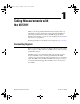
CBIHWum.book Page 1 Thursday, October 29, 1998 1:56 PM Taking Measurements with the NI 5911 1 Thank you for buying a National Instruments 5911 digital oscilloscope with flexible resolution. The NI 5911 offers unsurpassed flexibility for performing measurements from DC to 100 MHz. Using the NI 5911 flexible resolution feature, you can choose the sampling rate and resolution best suited to your application. Detailed specifications for the NI 5911 are in Appendix A, Specifications.
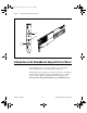
CBIHWum.book Page 2 Thursday, October 29, 1998 1:56 PM Chapter 1 Taking Measurements with the NI 5911 CH0 PFI1 PFI2 (DIN) Figure 1-1. NI 5911 Connectors Introduction to the VirtualBench-Scope Soft Front Panel The VirtualBench-Scope soft front panel allows you to interactively control your NI 5911 as you would a desktop oscilloscope. The following sections explain how to make connections to your NI 5911 and take simple measurements using the VirtualBench-Scope soft front panel, as shown in Figure 1-2.
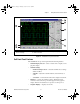
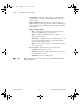
CBIHWum.book Page 3 Thursday, October 29, 1998 1:56 PM Chapter 1 Taking Measurements with the NI 5911 1 2 8 3 4 7 5 6 1 2 3 Channel Display Selector Channel Settings Selector Channel Settings 4 5 6 Trigger Setting Group Vertical Slider Main Control Bar 7 8 Zoom Controls Graphics Display Figure 1-2.
CBIHWum.book Page 4 Thursday, October 29, 1998 1:56 PM Chapter 1 Taking Measurements with the NI 5911 • Vertical Slider—adjusts the voltage offset for each channel. Use this slider when you want to adjust multiple waveforms in the graphics display. • Trigger Settings Group — controls the conditions required for signal acquisition; for example, whether to wait for a digital trigger before acquiring data or whether to acquire data in free-run mode (no triggering).
CBIHWum.book Page 5 Thursday, October 29, 1998 1:56 PM Chapter 1 Taking Measurements with the NI 5911 Using the VirtualBench-SCOPE Soft Front Panel The following sections describe how to perform simple analog input measurements using the VirtualBench-SCOPE soft front panel. Acquiring Data When you launch VirtualBench-Scope, it operates in continuous run mode. You can start acquiring signals with VirtualBench-Scope by completing the following steps: 1. Connect a signal to Channel 0 of your NI 5911. 2.
CBIHWum.book Page 6 Thursday, October 29, 1998 1:56 PM Chapter 1 Taking Measurements with the NI 5911 Device Type Selector Device List Figure 1-3. Acquire Tab of VirtualBench-Scope Settings Dialog Box Note: Note: NI 5911 User Manual When you launch VirtualBench-Scope, it automatically uses the settings of your previous VirtualBench-Scope session. 3. Enable the Ch 0 button in the Channel Selector group. Disable all other channels. 4. Click on AutoSetup on the main control bar. 5.
CBIHWum.book Page 1 Thursday, October 29, 1998 1:56 PM 2 Hardware Overview This chapter includes an overview of the NI 5911, explains the operation of each functional unit making up your NI 5911, and describes the signal connections. Figure 2-1 shows a block diagram of the NI 5911.
CBIHWum.book Page 2 Thursday, October 29, 1998 1:56 PM Chapter 2 Hardware Overview Measurement Fundamentals The NI 5911 has a differential programmable gain input amplifier (PGIA) at the analog input. The purpose of the PGIA is to accurately interface to and scale the signal presented at the connector to the analog-to-digital converter (ADC) regardless of source impedance, source amplitude, DC biasing or common-mode noise voltages.
CBIHWum.book Page 3 Thursday, October 29, 1998 1:56 PM Chapter 2 Hardware Overview the cable impedances you use. As a result, most of the noise voltage occurs at the negative input of the PGIA where it is rejected, rather than in the positive input, where it would be amplified. Input Ranges To optimize the ADC resolution, you can select different gains for the PGIA. In this way, you can scale your input signal to match the full input range of the converter.
CBIHWum.book Page 4 Thursday, October 29, 1998 1:56 PM Chapter 2 Hardware Overview Input Bias The inputs of the PGIA typically draw an input bias current of 1 nA at 25° C. Attaching a device with a very high source impedance can cause an offset voltage to be added to the signal you measure, according to the formula Rs × 1 nA, where Rs is the external source impedance.
CBIHWum.book Page 5 Thursday, October 29, 1998 1:56 PM Chapter 2 Hardware Overview Oscilloscope Mode In the oscilloscope mode, the NI 5911 works as a conventional desktop oscilloscope. This mode is useful for displaying waveforms and for deriving waveform parameters such as slew rate, rise time, and settling time. The sample resolution in oscilloscope mode is 8 bits. The ADC converts at a constant rate of 100 MS/s, but you can choose to store only a fraction of these samples into memory at a lower rate.
CBIHWum.book Page 6 Thursday, October 29, 1998 1:56 PM Chapter 2 Hardware Overview Table 2-2. Available Sampling Rates and Corresponding Bandwidth in Flexible Resolution Mode Sampling Rate Resolution Bandwidth 12.5 MS/s 12 bits 4 MHz 5 MS/s 14 bits 2 MHz 2.
CBIHWum.book Page 7 Thursday, October 29, 1998 1:56 PM Chapter 2 Hardware Overview sampling rates, resolutions, and bandwidth for flexible resolution mode are shown in Table 2-2. During the acquisition, samples are stored in a circular buffer that is continually rewritten until a trigger is received. After the trigger is received, the NI 5911 continues to acquire posttrigger samples if you have specified a posttrigger sample count. The acquired samples are placed into onboard memory.
CBIHWum.book Page 8 Thursday, October 29, 1998 1:56 PM Chapter 2 Hardware Overview Note 3. The linearity of the ADC is calibrated using an internal sinewave generator as reference. 4. The time-to-digital converter used for RIS measurements is calibrated. Do not apply high-amplitude or high-frequency signals to the NI 5911 during internal calibration. For optimal calibration performance, disconnect the input signal from the NI 5911.
CBIHWum.book Page 9 Thursday, October 29, 1998 1:56 PM Chapter 2 Analog Input High Level Gain + COMP Analog Trigger Circuit Low Level Hardware Overview ATC_OUT COMP – a. Analog Trigger Circuit Software ATC_OUT RTSI <0..6> PFI1, PFI2 Trigger 7 2 Arm b. Trigger and Arm Sources Figure 2-3. Trigger Sources Analog Trigger Circuit The analog trigger on the NI 5911 operates by comparing the current analog input to an onboard threshold voltage.
CBIHWum.book Page 10 Thursday, October 29, 1998 1:56 PM Chapter 2 Hardware Overview Trigger Value Falling Edge Trigger Rising Edge Trigger Figure 2-4. Below-Level Analog Triggering Mode In below-level analog triggering mode, the trigger is generated when the signal value is less than triggerValue. hysteresisValue is unused. Trigger Value Falling Edge Trigger Rising Edge Trigger Figure 2-5.
CBIHWum.book Page 11 Thursday, October 29, 1998 1:56 PM Chapter 2 Hardware Overview Trigger Value Hysteresis Value Trigger Falling Edge Trigger Rising Edge Trigger Figure 2-6. High-Hysteresis Analog Triggering Mode In high-hysteresis analog triggering mode, the trigger is generated when the signal value is greater than triggerValue, with the hysteresis specified by hysteresisValue. The signal must cross back below the hysteresisValue before another trigger is generated.
CBIHWum.book Page 12 Thursday, October 29, 1998 1:56 PM Chapter 2 Hardware Overview When a trigger is received during acquisition, the trigger counter is loaded with the desired hold-off time. Hardware then rejects all triggers until the counter has expired or the current acquisition completes, whichever is longer. The time the acquisition takes to complete from the time a trigger occurs is (posttrigger samples) / (sample rate(MHz)).
CBIHWum.book Page 13 Thursday, October 29, 1998 1:56 PM Chapter 2 Hardware Overview Multiple Record After the trigger has been received and the posttrigger samples have been stored, the NI 5911 can be configured to begin another acquisition that is stored in another memory record on the board. This is a multiple record acquisition. To perform multiple record acquisitions, the NI 5911 is configured to the number of records to be acquired before starting the acquisition.
CBIHWum.book Page 14 Thursday, October 29, 1998 1:56 PM Chapter 2 Hardware Overview fact that this condition has occurred may not be obvious by inspecting the acquired data due to the digital filtering that takes place on the acquired data. Therefore an error will occur to let you know that the data includes some samples that were out of the range of the converter and may be inaccurate.
CBIHWum.book Page 15 Thursday, October 29, 1998 1:56 PM Chapter 2 Hardware Overview Synchronization The NI 5911 uses a digital phase lock loop to synchronize the 100 MHz sample clock to a 10 MHz reference. This reference frequency can be supplied by a crystal oscillator on the board or through an external frequency input through the RTSI bus clock line or a PFI input.
CBIHWum.book Page 1 Thursday, October 29, 1998 1:56 PM A Specifications This appendix lists the specifications of the NI-5911. These specifications are typical at 25° C unless otherwise specified. NI 5911 Acquisition System Bandwidth .............................................. 100 MHz maximum, at all input ranges Number of channels ............................... 1 for PCI, 2 for VXI Number of flexible resolution ADC....... 1 for PCI, 2 for VXI Max sample rate .....................................
CBIHWum.book Page 2 Thursday, October 29, 1998 1:56 PM Appendix A Specifications Sampling Frequency Mode Sample depth (4 MB option) Sample depth (16 MB option) 200 kHz Flexible Resolution 1 MS 4 MS 100 kHz Flexible Resolution 1 MS 4 MS 50 kHz Flexible Resolution 1 MS 4 MS 20 kHz Flexible Resolution 1 MS 4 MS 10 kHz Flexible Resolution 1 MS 4 MS * 1
CBIHWum.book Page 3 Thursday, October 29, 1998 1:56 PM Appendix A Specifications Acquisition Characteristics Accuracy Amplitude accuracy ............................... ± 0.05% signal ± 0.0001% fs (5 to 40° C) for all input ranges at 1 kHz (excluding ripple from digital filters) DC offset ................................................ 0.1 mV + 0.01% fs (5° C to 40° C) for all input ranges Input coupling ........................................
CBIHWum.book Page 4 Thursday, October 29, 1998 1:56 PM Appendix A Specifications Filtering Sampling Frequency Filter Mode Bandwidth Ripple Alias Attenuation 100 MHz/n Oscilloscope 100 MHz ±3 dB N/A 12.5 MHz Flexible Resolution 3.75 MHz ±0.2 dB –60 dB 5 MHz Flexible Resolution 2 MHz ±0.1 dB –70 dB 2.5 MHz Flexible Resolution 1 MHz ±0.05 dB –80 dB 1 MHz Flexible Resolution 400 kHz ±0.005 dB –80 dB 500 kHz Flexible Resolution 200 kHz ±0.
CBIHWum.book Page 5 Thursday, October 29, 1998 1:56 PM Appendix A Specifications Dynamic Range Noise (excluding input-referred noise) Bandwidth Noise Density Total Noise 100 MHz/n 100 MHz –120 dBfs/sqrt(Hz) –43 dBfs 12.5 MHz 3.75 MHz –135 dBfs/sqrt(Hz) –64 dBfs 5 MHz 2 MHz –150 dBfs/sqrt(Hz) –83 dBfs 2.
CBIHWum.book Page 6 Thursday, October 29, 1998 1:56 PM Appendix A Specifications Timebase System Number of timebases ..............................2, RTSI clock configured as a 10 MHz clock output (Master), or RTSI clock configured as a 10 MHz reference clock input (Slave). Clock accuracy (as Master) ....................10 MHz ± 50 ppm Clock input tolerance (as Slave) .............10 MHz ± 100 ppm Clock jitter ..............................................
CBIHWum.book Page 7 Thursday, October 29, 1998 1:56 PM Appendix A Specifications Hysteresis ............................................... Full-scale voltage/n, where n is between 1 and 170; full-scale voltage on TRIG is fixed to ±5 V (without external attenuation) Coupling................................................. AC/DC on CH0, TRIG Pretrigger depth...................................... 1 to 16 million samples Posttrigger depth ....................................
CBIHWum.book Page 8 Thursday, October 29, 1998 1:56 PM Appendix A Specifications Physical Dimensions .............................................33.8 x 9.9 cm (13.3 x 3.9 in) I/O connectors Analog input CH0............................BNC female Digital triggers.................................SMB female, 9-pin DIN Operating Environment Ambient temperature ..............................5 to 40° C Relative humidity ...................................
CBIHWum.book Page 1 Thursday, October 29, 1998 1:56 PM B Digitizer Basics This appendix explains basic information you need to understand about making measurements with digitizers, including important terminology. Understanding Digitizers To understand how digitizers work, you should be familiar with the Nyquist theorem and how it affects analog bandwidth and sample rate.
CBIHWum.book Page 2 Thursday, October 29, 1998 1:56 PM Appendix B Digitizer Basics Analog Bandwidth Analog bandwidth describes the frequency range (in Hertz) in which a signal can be digitized accurately. This limitation is determined by the inherent frequency response of the input path which causes loss of amplitude and phase information. Analog bandwidth is the frequency at which the measured amplitude is 3 dB below the actual amplitude of the signal.
CBIHWum.book Page 3 Thursday, October 29, 1998 1:56 PM Appendix B Digitizer Basics 1µ = Sample Rate 2 MS/s = Sample Rate 20 MS/s Figure B-3. 1 MHz Sine Wave Sample Vertical Sensitivity Vertical sensitivity describes the smallest input voltage change the digitizer can capture. This limitation is because one distinct digital voltage encompasses a range of analog voltages. Therefore, it is possible that a minute change in voltage at the input is not noticeable at the output of the ADC.
CBIHWum.book Page 4 Thursday, October 29, 1998 1:56 PM Appendix B Digitizer Basics ADC Resolution ADC resolution limits the accuracy of a measurement. The higher the resolution (number of bits), the more accurate the measurement. An 8-bit ADC divides the vertical range of the input amplifier into 256 discrete levels. With a vertical range of 10 V, the 8-bit ADC cannot resolve voltage differences smaller than 39 mV.
CBIHWum.book Page 5 Thursday, October 29, 1998 1:56 PM Appendix B Digitizer Basics to Appendix A, Specifications, for the maximum input voltage for your NI 5911 device. Figure B-5 shows that a gain of 5 is the best setting to digitize a 300 mV, 1 MHz sine wave without clipping the signal. +127 LSB 0 LSB +7 LSB –8 LSB –128 LSB a. Gain = 1, Input Range ±5 V, Number of LSBs = 15 +127 LSB +38.4 LSB 0 LSB –38.4 LSB –128 LSB b.
CBIHWum.book Page 6 Thursday, October 29, 1998 1:56 PM Appendix B Digitizer Basics • Source impedance—Most digitizers and digital storage oscilloscopes (DSOs) have a 1 MΩ input resistance in the passband. If the source impedance is large, the signal will be attenuated at the amplifier input and the measurement will be inaccurate. If the source impedance is unknown but suspected to be high, change the attenuation ratio on your probe and acquire data.
CBIHWum.book Page 7 Thursday, October 29, 1998 1:56 PM Appendix B Digitizer Basics Ideally, the trigger event should occur at condition one, but sometimes the instrument may trigger on condition two because the signal crosses the trigger level. You can solve this problem without using complicated signal processing techniques by using trigger hold-off, which lets you specify a time from the trigger event to ignore additional triggers that fall within that time.
CBIHWum.book Page 1 Thursday, October 29, 1998 1:56 PM Customer Communication C For your convenience, this appendix contains forms to help you gather the information necessary to help us solve your technical problems and a form you can use to comment on the product documentation. When you contact us, we need the information on the Technical Support Form and the configuration form, if your manual contains one, about your system configuration to answer your questions as quickly as possible.
CBIHWum.book Page 2 Thursday, October 29, 1998 1:56 PM Fax-on-Demand Support Fax-on-Demand is a 24-hour information retrieval system containing a library of documents on a wide range of technical information. You can access Fax-on-Demand from a touch-tone telephone at 512 418 1111. E-Mail Support (Currently USA Only) You can submit technical support questions to the applications engineering team through e-mail at the Internet address listed below.
CBIHWum.book Page 3 Thursday, October 29, 1998 1:56 PM Technical Support Form Photocopy this form and update it each time you make changes to your software or hardware, and use the completed copy of this form as a reference for your current configuration. Completing this form accurately before contacting National Instruments for technical support helps our applications engineers answer your questions more efficiently.
CBIHWum.book Page 5 Thursday, October 29, 1998 1:56 PM NI 5911 Hardware and Software Configuration Form Record the settings and revisions of your hardware and software on the line to the right of each item. Complete a new copy of this form each time you revise your software or hardware configuration, and use this form as a reference for your current configuration.
CBIHWum.book Page 7 Thursday, October 29, 1998 1:56 PM Documentation Comment Form National Instruments encourages you to comment on the documentation supplied with our products. This information helps us provide quality products to meet your needs. Title: NI 5911 User Manual Edition Date: October 1998 Part Number: 322150A-01 Please comment on the completeness, clarity, and organization of the manual.
CBIHWum.
CBIHWum.book Page 2 Thursday, October 29, 1998 1:56 PM Glossary A/D analog-to-digital ADC analog-to-digital converter—an electronic device, often an integrated circuit, that converts an analog voltage to a digital number ADC resolution the resolution of the ADC, which is measured in bits. An ADC with16 bits has a higher resolution, and thus a higher degree of accuracy, than a 12-bit ADC.
CBIHWum.book Page 3 Thursday, October 29, 1998 1:56 PM Glossary DC direct current default setting a default parameter value recorded in the driver. In many cases, the default input of a control is a certain value (often 0) that means use the current default setting.
CBIHWum.book Page 4 Thursday, October 29, 1998 1:56 PM Glossary I in. inches inductance the relationship of induced voltage to current input bias current the current that flows into the inputs of a circuit input impedance the measured resistance and capacitance between the input terminals of a circuit instrument driver a set of high-level software functions that controls a specific plug-in DAQ board.
CBIHWum.book Page 5 Thursday, October 29, 1998 1:56 PM Glossary O Ohm’s Law (R=V/I)—the relationship of voltage to current in a resistance overrange a segment of the input range of an instrument outside of the normal measuring range. Measurements can still be made, usually with a degradation in specifications.
CBIHWum.
CBIHWum.
CBIHWum.book Page 1 Thursday, October 29, 1998 1:56 PM Index A low-hysteresis analog triggering mode (figure), 2-11 trigger hold-off, 2-11 to 2-12 VirtualBench-Scope soft front panel, 1-5 to 1-6 ADC resolution, B-4 analog bandwidth, B-2 analog trigger circuit, 2-9 to 2-11 above-level analog triggering mode (figure), 2-10 below-level analog triggering mode (figure), 2-10 high-hysteresis analog triggering mode (figure), 2-11 low-hysteresis analog triggering mode (figure), 2-11 arming.
CBIHWum.
CBIHWum.book Page 3 Thursday, October 29, 1998 1:56 PM Index N measurement fundamentals, 2-2 to 2-4 measurement modes, 2-4 to 2-6 flexible resolution mode, 2-5 to 2-6 oscilloscope mode, 2-5 hysteresis value. See analog trigger circuit. NI 5911. See also hardware overview.
CBIHWum.