
User Guide

© National Instruments Corporation 1-1 NI 5911 User Manual
1
Taking Measurements
with the NI 5911
Thank you for buying a National Instruments (NI) 5911 digitizer, featuring
the FLEX ADC. This chapter provides information on installing,
connecting signals to, and acquiring data from your NI 5911.
Installing the NI 5911
There are two main steps involved in installation:
1. Install the NI-SCOPE driver software. You use this driver to write
programs to control your NI 5911 in different application development
environments (ADEs). Installing NI-SCOPE also allows you to
interactively control your NI 5911 with the Scope Soft Front Panel.
2. Install your NI 5911. For step-by-step instructions for installing
NI-SCOPE and the NI 5911, see Where to Start with Your NI Digitizer.
For multiple-board considerations, see the Operating Environment section
in Appendix A, Specifications, of this manual.
Connecting Signals
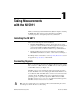
Figure 1-1 shows the front panel for the NI 5911. The front panel contains
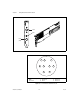
three connectors—a BNC connector, an SMB connector, and a 9-pin mini
circular DIN connector (see Figure 1-2).
The BNC connector is for attaching the analog input signal you wish to
measure. The BNC connector is analog input channel 0. To minimize noise,
do not allow the shell of the BNC cable to touch or lie near the metal of the
computer chassis. The SMB connector is for external triggers and for
generating a probe compensation signal. The SMB connector is PFI1.
The DIN connector gives you access to an additional external trigger line.
The DIN connector can be used to access PFI2.
Note
The +5 V signal is fused at 1.1 A. However, NI recommends limiting the current
from this pin to 30 mA. The fuse is self-resetting.