OPERATING INSTRUCTIONS AND SPECIFICATIONS NI 9476 32-Channel, 24 V, Sourcing Digital Output Module Français Deutsch ni.
This document describes how to use the National Instruments 9476 and includes specifications and pin assignments for the NI 9476. Visit ni.com/info and enter rdsoftwareversion to determine which software you need for the modules you are using. For information about installing, configuring, and programming the system, refer to the system documentation. Visit ni.com/info and enter cseriesdoc for information about C Series documentation.
Safety Guidelines Operate the NI 9476 only as described in these operating instructions. This icon denotes that the component may be hot. Touching this component may result in bodily injury. Hot Surface Safety Guidelines for Hazardous Locations The NI 9476 is suitable for use in Class I, Division 2, Groups A, B, C, D, T4 hazardous locations; Class I, Zone 2, AEx nC IIC T4, and Ex nC IIC T4 hazardous locations; and nonhazardous locations only.
Substitution of components may impair suitability for Class I, Division 2. Caution For Zone 2 applications, install the system in an enclosure rated to at least IP 54 as defined by IEC 60529 and EN 60529. Caution For Zone 2 applications, install a protection device between the external power supply and the Vsup pin. The device must prevent the Vsup-to-COM voltage from exceeding 50 V if there is a transient overvoltage condition.
Special Conditions for Marine Applications Some modules are Lloyd’s Register (LR) Type Approved for marine applications. To verify Lloyd’s Register certification, visit ni.com/certification and search for the LR certificate, or look for the Lloyd’s Register mark on the module. To meet radio frequency emission requirements for marine applications, use shielded cables and install the system in a metal enclosure.
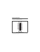
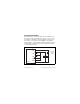
Connecting the NI 9476 The NI 9476 has a 37-pin DSUB connector that provides connections for 32 digital output channels. DO16 DO17 DO18 DO19 DO20 DO21 DO22 DO23 Vsup Vsup DO24 DO25 DO26 DO27 DO28 DO29 DO30 DO31 20 21 22 23 24 25 26 27 28 29 30 31 32 33 34 35 36 37 1 2 3 4 5 6 7 8 9 10 11 12 13 14 15 16 17 18 19 DO0 DO1 DO2 DO3 DO4 DO5 DO6 DO7 Vsup Vsup DO8 DO9 DO10 DO11 DO12 DO13 DO14 DO15 COM Figure 1. NI 9476 Pin Assignments NI 9476 Operating Instructions and Specifications 6 ni.
Each channel has a DO pin to which you can connect a digital input device. The 32 digital output channels are internally referenced to COM. You must connect an external power supply to the NI 9476. The power supply provides the current for the output channels. Connect the positive lead of the power supply to the supply pin, Vsup, and the negative lead of the power supply to the common pin, COM. Refer to the Specifications section for information about the power supply voltage range.
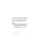
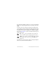
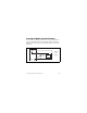
You can directly connect the NI 9476 to a variety of industrial devices such as solenoids, motors, actuators, relays, and lamps. Make sure the devices you connect to the NI 9476 are compatible with the output specifications of the module. Refer to the Specifications section for more information about the output specifications. Connect the device to DO and COM, and connect the external power supply to Vsup and COM, as shown in Figure 2. Vsup + External DO Device _ Power Supply COM NI 9476 Figure 2.
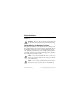
Increasing Current Drive Each channel has a continuous output current of 250 mA. If you want to increase the output current to a device, you can connect any number of channels together in parallel. For example, if you want to drive 1 A of current, connect DO<0..3> in parallel as shown in Figure 3. You must turn all parallel channels on and off simultaneously so that the current on any single channel cannot exceed the 250 mA rating.
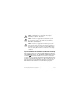
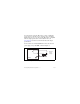
Protecting the Module from Flyback Voltages If the module is switching an inductive or energy-storing device such as a solenoid, motor, or relay, and the device does not have flyback protection, install an external flyback diode as shown in Figure 4. Vsup + External DO Flyback Diode Inductive Device _ Power Supply COM NI 9476 Figure 4. Connecting a Flyback Diode to the NI 9476 NI 9476 Operating Instructions and Specifications 10 ni.
I/O Protection The NI 9476 is protected against overcurrent, inrush, and short-circuit conditions in accordance with IEC 1131-2. Understanding Protected Devices Each channel on the NI 9476 has circuitry that protects it from voltage and current surges resulting from short circuits. Caution The NI 9476 can be damaged under overvoltage and reverse bias voltage conditions. Check the voltage specifications for all devices that you connect to the NI 9476.
Sleep Mode This module supports a low-power sleep mode. Support for sleep mode at the system level depends on the chassis that the module is plugged into. Refer to the chassis manual for information about support for sleep mode. If the chassis supports sleep mode, refer to the software help for information about enabling sleep mode. Visit ni.com/info and enter cseriesdoc for information about C Series documentation. Typically, when a system is in sleep mode, you cannot communicate with the modules.
Specifications The following specifications are typical for the range –40 to 70 °C unless otherwise noted. All voltages are relative to COM unless otherwise noted. Output Characteristics Number of channels.......................... 32 digital output channels Output type ....................................... Sourcing Output voltage (V0) ........................... Vsup – (I0R0) Power-on output state ....................... Channels off External power supply voltage range (Vsup)...........................
Continuous overvoltage protection (Vsup) ................................ up to 40 V max Reversed-voltage protection ............. None Current limiting ................................ None Short-circuit protection..................... Indefinitely protected when a channel is shorted to COM or to a voltage up to Vsup Trip current for one channel With all other channels at rated current............................ 3 A typ With all other channels off ......... 5 A typ Vsup current consumption ...............
MTBF ............................................... 1,091,425 hours at 25 °C; Bellcore Issue 2, Method 1, Case 3, Limited Part Stress Method Note Contact NI for Bellcore MTBF specifications at other temperatures or for MIL-HDBK-217F specifications. Power Requirements Power consumption from chassis Active mode ............................... 250 mW max Sleep mode ................................. 25 μW max Thermal dissipation (at 70 °C) Active mode ............................... 1.5 W max Sleep mode .....
Safety Maximum Voltage1 Connect only voltages that are within the following limits. Vsup-to-COM..................................... 36 VDC, Measurement Category 1 Measurement Category I is for measurements performed on circuits not directly connected to the electrical distribution system referred to as MAINS voltage. MAINS is a hazardous live electrical supply system that powers equipment. This category is for measurements of voltages from specially protected secondary circuits.
Isolation Voltages Channel-to-channel........................... No isolation between channels Channel-to-earth ground Continuous ................................. 60 VDC, Measurement Category I Withstand....................................
Hazardous Locations U.S. (UL) .......................................... Class I, Division 2, Groups A, B, C, D, T4; Class I, Zone 2, AEx nC IIC T4 Canada (C-UL) ................................. Class I, Division 2, Groups A, B, C, D, T4; Class I, Zone 2, Ex nC IIC T4 Europe (DEMKO)............................. EEx nC IIC T4 Environmental National Instruments C Series modules are intended for indoor use only but may be used outdoors if installed in a suitable enclosure.
Operating humidity (IEC 60068-2-56).............................. 10 to 90% RH, noncondensing Storage humidity (IEC 60068-2-56).............................. 5 to 95% RH, noncondensing Maximum altitude............................. 2,000 m Pollution Degree (IEC 60664) .......... 2 Shock and Vibration To meet these specifications, you must panel mount the system. Operating vibration Random (IEC 60068-2-64)......... 5 grms, 10 to 500 Hz Sinusoidal (IEC 60068-2-6) .......
Electromagnetic Compatibility This product is designed to meet the requirements of the following standards of EMC for electrical equipment for measurement, control, and laboratory use: • EN 61326 EMC requirements; Industrial Immunity • EN 55011 Emissions; Group 1, Class A • CE, C-Tick, ICES, and FCC Part 15 Emissions; Class A Note For EMC compliance, operate this device with shielded cabling. NI 9476 Operating Instructions and Specifications 20 ni.
CE Compliance This product meets the essential requirements of applicable European directives, as amended for CE markings, as follows: • 2006/95/EC; Low-Voltage Directive (safety) • 2004/108/EC; Electromagnetic Compatibility Directive (EMC) Note Refer to the Declaration of Conformity (DoC) for this product for any additional regulatory compliance information. To obtain the DoC for this product, visit ni.
For additional environmental information, refer to the NI and the Environment Web page at ni.com/environment. This page contains the environmental regulations and directives with which NI complies, as well as other environmental information not included in this document. Waste Electrical and Electronic Equipment (WEEE) EU Customers At the end of their life cycle, all products must be sent to a WEEE recycling center.
Where to Go for Support The National Instruments Web site is your complete resource for technical support. At ni.com/support you have access to everything from troubleshooting and application development self-help resources to email and phone assistance from NI Application Engineers. National Instruments corporate headquarters is located at 11500 North Mopac Expressway, Austin, Texas, 78759-3504. National Instruments also has offices located around the world to help address your support needs.
Korea 82 02 3451 3400, Lebanon 961 (0) 1 33 28 28, Malaysia 1800 887710, Mexico 01 800 010 0793, Netherlands 31 (0) 348 433 466, New Zealand 0800 553 322, Norway 47 (0) 66 90 76 60, Poland 48 22 3390150, Portugal 351 210 311 210, Russia 7 495 783 6851, Singapore 1800 226 5886, Slovenia 386 3 425 42 00, South Africa 27 0 11 805 8197, Spain 34 91 640 0085, Sweden 46 (0) 8 587 895 00, Switzerland 41 56 2005151, Taiwan 886 02 2377 2222, Thailand 662 278 6777, Turkey 90 212 279 3031, United Kingdom 44 (0) 1635 5