
Computer Hardware User Manual


1.0 Introduction
The LM95235 Evaluation Board is used together
with the National Semiconductor SensorEval
software (provided in the kit), and with a USB cable
(not provided in the kit), and with an external
personal computer (PC). Power to the LM95235
Evaluation Board is provided by the +5 VDC line of
the USB connection. No external power supply or
signal sources are required for operation of the
LM95235 evaluation board.
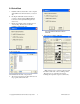
Before connecting the PC to the LM95235
evaluation board through the USB cable, the PC is
first turned on and allowed to go through its boot-up
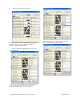
procedure. The user installs and initiates the
SensorEval software. See Section 4.0 for details.
After the SensorEval software is running, the user
can connect the USB cable first to the computer and
then to the LM95235 Evaluation Board.
The PC should be able to recognize the board and
the user simply selects the LM95235 Eval Board
radio button.
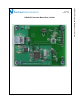
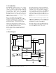
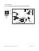
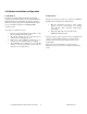
The block diagram below describes the LM95235
Evaluation Board itself. The USB input provides the
+5.0 VDC power to the board, which is regulated
down to 3.3 VDC to power the IC’s. The EEPROM
is programmed at the factory with a unique ID code
for this particular board. When the USB cable is
plugged in, the PC interrogates the USB devices and
can identify this device as the LM95235 Evaluation
Board.
The microcontroller on the board provides the serial
SMBus clock (SMBCLK), provides the SMBus data
(SMBDAT) signal, and relays the information from
the LM95235 to the PC via the USB lines.
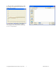
The block in the lower right of the Block Diagram
shows the signals that are available to probe by the
user for the LM95235 device on the board.
1.1 Block Diagram
USB
Input
EEPROM
Circuit
Voltage
Regulator
Circuit
Microcontroller
Circuitry
USB D+
USB D-
SMBCLK
SMBDAT
+5.0 VDC
GND
+3.3 VDC
VDD
GND
GND
GND
SMBCLK
SMBDAT
T_Crit
OS/A0
U2
LM95235
© Copyright 2006 National Semiconductor Corporation 4 www.national.com