
Computer Hardware User Manual


© Copyright 2006 National Semiconductor Corporation 9 www.national.com
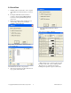
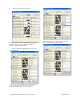
3.0 Functional Description
The LM95235 Evaluation Board, along with the
SensorEval Software, provides the system designer
with a convenient way to learn about the operation of
the LM95235 Temperature Sensor chip. The user
simply has to install the SensorEval software on his
PC, run it, connect the USB cable from the PC to the
Evaluation Board, and the user can read the
temperatures. It’s that simple! The user doesn’t have
to provide any power or external signals to the
evaluation board.
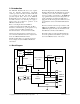
Power to the LM95235 Evaluation Board is taken
from the USB 5-Volt line. This +5 VDC is the input
to the on-board LM2950 low dropout voltage
regulator, which regulates the output voltage to +3.3
VDC. This output voltage powers the LM95235, the
on-board microcontroller, and the EEPROM chip
where the board ID information is stored.
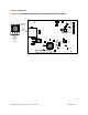
The microcontroller provides the SMBus Clock
(SMBCLK) signal and the SMBus Data (SMBDAT)
signal to the LM95235 chip. This communication
between the LM95235 and the PC USB data lines is
controlled by the microcontroller. For all of the
details of this communication protocol see the latest
LM95235 datasheet, available at www.national.com.
3.1 LM95235 Evaluation Board Connection Table
Connector Label Pin
Number
Description
J1 N/A
USB Cable Input. Connect the USB cable to this jack after
the SensorEval software has been loaded on the PC.
1
V
DD
. The +3.3 VDC voltage supplied by the on-board
voltage regulator to the LM95235 V
DD
input pin. Do not
connect an external power supply to this pin!
2 SMBDAT. Data signal for the SMBus.
3 SMBCLK. Clock signal for SMBus.
4
OS#/A0. When this pin is pulled low it enables the
Overtemperature Shutdown (OS) feature. When this pin is
pulled high it is the Address pin function.
5 No Connection.
6
T_Crit#. This is the signal that goes low when the Set
Temperature is exceeded.
JP2
Output header provides
user with signals for test
purposes only.
Do not apply any
external power or
signals to any of the
pins on these headers!
7 No Connection.
3, 4 Connect for D+ connection
J4
Connection to
temperature diodes
Do not apply any
external power or
signals to any of the
pins on these headers!
1, 2 Connect for D- connection