
User guide

Page 7
Inverter-Charger
(IC1230150)
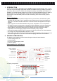
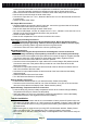
Typical Wiring block diagram of the Inverter-Charger
12V Battery Bank:
• The use of a deep cycle battery is highly recommended for power inverter application.
• For battery size, you need to identify what you wish to operate, and for how long. Nature
Power recommends that you purchase as much battery capacity as possible. See more on
Estimated Run Times in Section 4.
DC Cable:
• All DC cables used require multi-strand insulated cable.
• The DC cables must be copper and must be rated 105°C minimum.
• Based on National Electrical Code, cable size of 4/0 AWG is required for cable length < 5 ft.
Use of smaller gauge cable or longer cable length may cause the inverter to shutdown under
heavy load and may also melt the cable insulation and catch fire and can result in death or
serious injury.
DC Grounding:
• The chassis of the unit has to be grounded properly.
• For Marine application, the DC grounding cable size may be one size smaller than the
minimum size conductor required for the DC current carrying conductors, providing the
overcurrent protection device in the DC positive conductor is rated no greater than 135% of
the capacity of the DC grounding conductor, and the conductor is no smaller than #16AWG.
• For Recreational Vehicle application, the unit has to be grounded to the vehicle chassis with a
minimum #8 AWG copper conductor with either green insulator or bare wire.
Important: The unit is grounded through the ground stud of the unit .
DC Fuse or Over Current Protective Device:
• A DC-rated fuse or a DC-rated over-current protective device connected along the DC positive
line is required.
• Based on the National Electrical Code requirement, a fuse or circuit breaker with a minimum of
350 Adc is required.
• Based on the size of your 12V Battery Bank, determine the overall short circuit current rating
of the battery bank from the battery manufacturer. The fuse or circuit breaker chosen must be
able to withstand the short circuit current that may be generated by the battery bank.
• For Marine application, the over current protective device needs to be installed within 7 inches
(17.8cm) from the battery positive terminals.
DC Disconnect Switch:
• Select a DC Disconnect Switch with the same or higher rating of the selected fuse or over
current protective device.
• The DC Disconnect Switch is used to disconnect the DC power between the unit and the
battery bank during service, maintenance or trouble shooting.
Main AC Input Panel (wire size and breaker size):
• For Dual AC Input, #6 AWG AC Input wire is required.
• For Split Phase AC Input, #10 AWG AC Input Wire is required for all the AC connections
between the AC source and the AC Input port.
• To meet CSA, UL and electrical code requirements and to protect system wiring, the AC input
line must be provided with an overcurrent protection device for which a 30A branch circuit
breaker is required to connect each AC Line to the unit’s AC Input.
DC
Disconnect
Switch
DC Fuse or Over
Current Protective
Device
12V
Battery
Bank
Inverter
AC Output
Panel
(AC Output)
Main AC
Input Panel
(AC Input)
Input:
AC Source