Datahelm 8120 Installation and Operation Manual www.navman.
Contents 1 Introduction .............................................................................................................................................................................5 1-1 Overview . . . . . . . . . . . . . . . . . . . . . . . . . . . . . . . . . . . . . . . . . . . . . . . . . . . . . . . . . . . . . . . . . . . . . . . . . . . . . . . . . . . . . . . . . . . . . 6 1-2 Cleaning and maintenance . . . . . . . . . . . . . . . . . . . . . . . . . . . . . . . . . . . . . . . . . .
10-4 Sonar 50/200 window . . . . . . . . . . . . . . . . . . . . . . . . . . . . . . . . . . . . . . . . . . . . . . . . . . . . . . . . . . . . . . . . . . . . . . . . . . . . . . 43 10-5 Sonar A-Scope window . . . . . . . . . . . . . . . . . . . . . . . . . . . . . . . . . . . . . . . . . . . . . . . . . . . . . . . . . . . . . . . . . . . . . . . . . . . .44 11 Gauges window ...................................................................................................................................
Appendix A - Specifications ......................................................................................................................................................... 81 Appendix B - Troubleshooting .....................................................................................................................................................83 B-1 General problems . . . . . . . . . . . . . . . . . . . . . . . . . . . . . . . . . . . . . . . . . . . . . . . . . . . . . . . . . . . . . . .
1 Introduction Quick reference to the built-in and optional features: Feature General Type How to use the keys and windows Troubleshooting Simulate mode Glossary of special names Specifications MOB Man overboard key Navigation Overview of how to navigate Finding the boat’s position on the chart Navigate to any point or to a waypoint Navigate along a route Projected course: An estimate of progress Tracks: records of where the boat has been GPS receiver status Saving and loading data with a user card Chart da
1-1 Overview The NAVMAN 8120 is a rugged, highly integrated marine chartplotter and fishfinder. It is easy to use and has a very large, easy to read and use colour display. Complex functions can be performed with only a few key presses, taking the hard work out of boating. The available functions depend on the optional sensors and instruments that are installed: The Video window requires the 8120 to receive video from a compatible source, such as a camera.
! WARNING DANGER 1-3 Plug-in cards The 8120 can use two kinds of C-MAP™ SD-Card plug-in cards: Chart cards have chart details required for navigating in a particular region. When you insert a chart card, the extra details automatically appear on the Chart window. You can plug in up to two chart cards at once. If the chart shows a region not covered by a chart card, then it displays a simplified built-in world chart. User cards store navigation data.
1-4 Removing and replacing the display unit If the 8120 is bracket mounted then it can easily be removed for security. Removing the display unit: 1 Turn the 8120 off (see section 2-2) and put the dust cover on. 2 Loosen the knobs on the mounting bracket and lift the unit off the bracket. 3 Unplug the connectors from the 8120; turn each locking collar anticlockwise until you can pull the plug out. 4 Store the 8120 in a dry clean place.
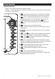
2 Basic Operation Overview of the keys Display – All windows and the data header/Compass Window – A part of the display in which a particular function is shown eg. The Chart window on a Chart + Sonar display. 1 2 5 6 3 4 7 8 9 10 11 12 13 9 ESC – Go back to an earlier menu or window. Any changes are ignored. In chart mode centers chart at boat’s position. DISPLAY – This is a powerful key that allows you to setup the display the way you want.
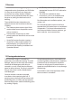
2-1 Using the keys In this manual: Press means to push the key for less than a second. Hold means to hold the key down. The internal beeper beeps when a key is pressed (to adjust the beep volume, see section 19-1). Using the menus Operate the Instrument by selecting items from menus. Items can be submenus, commands or data. Selecting a submenu A after a menu item indicates a submenu, for example Chart . Press or to move the highlight to the submenu, then press ENTER .
2-2 Turning on and off / auto power Turning on manually If the Instrument is not wired for auto power, press to turn the unit on. If necessary, adjust the display to be easy to read (see section 2-3). ! CAUTION ! WARNING If the Instrument is not wired for auto power then theDANGER Instrument does not record engine hours and will not record CAUTION fuel consumption if not powered (see section 18-4).
2-4 Man overboard (MOB) The MOB feature saves the boat’s position ! CAUTION and then navigates back to this point. ! WARNING MOB will not work if the Instrument does DANGER not have a GPS fix. CAUTION 1 Press The Instrument stores the boat’s position as a waypoint called MOB. 2 The Instrument changes to the chart window, with the MOB waypoint at the centre of the chart. The chart zooms in for accurate navigation.
2-7 The main windows To show one of the main windows full-size, press DISPLAY and select the window. Note 1 The windows available depend on the optional sensors and instruments that are installed (see section 1-1). 2 Set up commonly used windows as favourites and press to switch between windows (see section 2-7-2).
To show one of the other windows fullscreen, press DISPLAY , select More... and select the window. Press ESC to return from one of these windows to the previous window.
2-7-1 Multi window displays The 8120 can show up to four windows at once, for example Chart, Sonar, Gauges and Video: Adding a window to the display Press DISPLAY , select Add window and select a window to add. The 8120 automatically rearranges the display to show the new window. Changing window size 1 Press DISPLAY and select Split ratio. 2 Press or to change the width of the windows. If the 8120 is displaying three or four windows, press or to change the height of the windows.
2-7-2 Favourite displays The 8120 has a list of commonly used displays, called favourite displays. There can be up to six favourite displays. Each display can have one or more windows plus a data header (see section 2-7-3) and a compass (see section 2-7-4). Set up favourite displays for common situations, for example navigating along a route, travelling in a harbour, fishing. Selecting a favourite display To select another favourite, press one or more times.
2-7-3 Data header The displays can show data at the top, called the data header. When you select a window from the display menu (see section 2-7) the 8120 displays an appropriate data header for the window. Each favourite display (see section 2-7-2) has its own data header. When you press to recall a favourite display, the 8120 recalls the favourite displays data header. Setting the data header for a display 1 Press DISPLAY and select Data header. 2 To turn the data header on or off: i Select Data.
3 Navigation: Chart The chart window shows the chart, the boat’s position course and navigation data. 3-1 Introduction to navigating The Instrument has two ways of navigating, going straight to a point or following a route. 3-1-1 Navigating to a point When the Instrument is navigating to a point, the chart and highway windows show navigation data: A The boat position . B The destination point marked with a circle. C The boat’s plotted course to the destination.
3-1-2 Going to a waypoint or to a point on the chart A waypoint is a position that you can set on the Instrument chart, for example a fishing spot or a point on a route (see section 5). Going to a waypoint from the chart window 1 Go to the chart window. 2 Move the cursor to the waypoint: either use the cursor keys or use Find (see section 3-2-5). AUTO 3 Press GOTO Going to a waypoint from the waypoints window 1 Go to the waypoints window. 2 Press or to highlight the waypoint to go to.
3-2 Chart window To go to the Chart window: Press DISPLAY and select Chart A typical chart window shows: A B C K F D J E I G A Data header. To turn the data off or on or to change what data is displayed (see section 2-7-3) B Compass (see section 2-7-4) C Chart scale (see section 3-2-3) D Boat position (see section 3-2-1) E Boat track (see section 3-5) F Boat course and CDI lines (see Appendix C, CDI).
3-2-1 Chart modes The Chart has two modes: Centre on boat mode To switch to centre on boat mode in the chart window, press ESC . The boat is at the centre of the chart. As the boat moves through the water, the chart automatically scrolls to keep the boat in the centre of the chart. The cursor (see below) is turned off. Cursor mode The keys and are called cursor keys. To switch to cursor mode in the chart window, hold down a cursor key.
3-2-5 Finding a chart symbol To find and display a chart symbol: 1 Press MENU and select Find. 2 Select the type of symbol: Waypoints, Routes, Ports by name, Ports & services, or Tide stations. 3 For Ports & services: select the type of service to find. For Ports by name: press , , or to enter a name or letters contained in the port name, then press ENTER . 4 A list of items is displayed. If there are more items than will fit on the window, press or to page up and down.
3-4 Projected course If Projected course is turned on, then the Instrument will display the projected position based on the course over ground (COG), speed and a specified time. To turn Projected course on and off and to set the time, see section 17-2. A Projected position B Boat’s projected course C Boat position A B C 3-5 Tracks and tracking Tracking records the boat’s position to memory at regular intervals, which can be: Time intervals. Or distance intervals.
4 Video window The video window shows a picture from a video device, such as a camera. The video window requires a video device to be installed. To select the video window, press DISPLAY and select Video. Adjusting the video picture colour 1 Press MENU . 2 Press or to highlight a control, then press or to adjust the control. 3 To return the colours to their default settings, select Restore defaults. 4 Press ESC .
5 Navigation: Highway window A B C D E F G The highway window has a bird’s eye view of the boat’s course to a destination: To go to the Highway window, press DISPLAY , select More, then select Highway. The highway window shows: A Optional data header (see section 2-7-3) B Optional compass (see section 2-7-4) C Destination waypoint D Boat’s plotted course to destination E CDI lines, parallel to the boat’s plotted course (see Appendix C, CDI).
6-1 Waypoints window To go to the waypoints window, press DISPLAY , select More, then select Waypoints. The waypoints window is a list of the waypoints that have been entered, each with waypoint symbol, name, latitude and longitude, distance and bearing from the boat, type and display option. If there are more waypoints than will fit on the window, press or to scroll up or down a page at a time.
6-2-4 Displaying a waypoint on the chart This goes to the chart window, and shows the selected waypoint at the centre of the window. 1 In the waypoints window, press or to highlight the waypoint to display. Press MENU and select Display. Or, in the Chart window, press MENU , select Find, then select Waypoints. Select a waypoint from the list. 2 The Instrument switches to the chart window, with the selected waypoint at the centre of the chart.
7 Navigation: Routes A route is a list of waypoints that the boat can navigate along. Routes can be created, changed and deleted. The Instrument can have up to 25 routes. Each route can have up to 50 waypoints. A route can: Start and stop at the same waypoint . Include waypoints more than once. The Instrument can navigate along a route in either direction. Waypoints on the route can be skipped.
ii A waypoint is created with a default name. to save this waypoint press ENTER , to edit the waypoint refer to 5-2-7 iii Press ENTER a dotted leg line is displayed from the cursor to the previous waypoint iv Move the cursor to the end of the first leg and press ENTER . v Repeat i to iv until the last waypoint in the route is placed and saved vi Press ESC to complete the route Menu options while creating a route: 1 To add a waypoint to the route i Press MENU and select Add.
7-2-2 Editing a route Editing a route from the chart 1 In the routes window, select the route to edit. Press MENU and select Edit on chart. 2 The selected route is displayed on the chart, with a circle around the first waypoint. 3 Edit the route as described in section 6-2-1 A, starting at step 4. Editing a route from the routes window 1 In the routes window, press or to highlight the route to edit. Press MENU and select Edit. 2 The selected route is displayed: the route name and a list of the waypoints.
8 Satellites GPS worldwide navigation The US Government operates the GPS system. Twenty-four satellites orbit the earth and broadcast position and time signals. The positions of these satellites are constantly changing. The GPS receiver analyses the signals from the closest satellites and calculates exactly where it is on earth. This is called the GPS position. The accuracy of the GPS position is typically better than 10 m (33 ft) for 95% of the time.
8-1 Satellite window The satellite window has information about the GPS satellites and GPS position. To go to the satellite window, press DISPLAY , select Other, then select Satellite. The satellite window shows: A B E C F G D A Status of GPS antenna, for example Acquiring, GPS fix, No GPS. If the unit is in Simulate mode it displays Simulate (see section 2-6). B Time and date from GPS satellites.
The appearance of echoes displayed are affected by: • The Instrument settings (see sections 17-3, 8-5 and 8-6) • Echoes (different fish types, different bottom types, wrecks and seaweed; see section 8-2) • Noise (water clarity and bubbles; see section 8-2). Cruise, Fishing and Manual Modes The Instrument has three sonar operating modes: • Cruising mode: Use this when on the move. The Instrument automatically adjusts its settings to compensate for water clarity and to display the bottom.
DANGER Strength of echoes The colours indicate differences in the strength of the echo. The strength varies with several factors, such as the: • Size of the fish, school of fish or other object. • Depth of the fish or object. • Location of the fish or object. (The area covered by the ultrasonic pulse is a rough cone shape and the echoes are strongest in the middle.) • Clarity of water. Particles or air in the water reduce the strength of the echo. • Composition or density of the object or bottom.
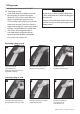
Shadows Shadows are created around areas where the ultrasonic beam cannot ‘see’. These areas include hollows on the bottom or beside rocks and ledges, where the strong echoes returned off the rocks obscure the weak echoes of the fish and may also create a double bottom trace. See following for an example of the sonar window in such an environment. A double bottom trace is shown on the window. When looking for fish with the wide angled 50 kHz frequency, be aware of increased shadows.
When to use Mixed The Mixed frequency combines the 200 kHz and the 50 kHz echoes on one sonar window, filling in detailed echoes in the centre of the sonar cone.
Comparison of the same fish scenario displayed at different frequencies: 1 minute ago 30 seconds ago Now 50 kHz display 200 kHz display 200/50 Khz display Mixed display 37 8120 Installation and Operation Manual
9-4 Fish detection and display Where to find fish Underwater features like reefs, wrecks and rocky outcrops attract fish. Use the 50 kHz or 50/200 kHz frequency window to find these features, then look for fish by passing over the feature slowly several times using the Zoom window (see section 9-2). If there is a current, the fish will often be found downstream of the feature. When fishing with the Instrument with the Fish symbols Off, a weak fuzzy band may appear between the bottom trace and surface.
• It is difficult to get fish arches in shallow water as the transducer sonar beam is very narrow near the surface and fish do not stay within the beam long enough to display an arch. Several fish in shallow water tend to display as randomly stacked areas of colour. • Wave motion may result in distorted fish arches. 23 Fun fish symbol Normal fish symbol Fun symbol + depth Fish arch + depth 9-5 Range Range is the vertical depth displayed on the Instrument sonar window.
9-6 Gain and threshold Gain and threshold settings control the amount of detail displayed on a sonar window: Gain: The gain of the sonar receiver. The gain should be high to display good detail, but if the gain is too high then information from the strong bottom signal is lost and false echoes might be displayed. There is a separate gain setting for each sonar frequency, 50 kHz and 200 kHz. Threshold: Return echoes less than the threshold are ignored.
10 Sonar fishfinding: Windows To show the Sonar window, press DISPLAY , then select Sonar. There are five kinds of sonar window. To use a window, press MENU , select Sonar splits, then select the type of window to use: No split: Sonar history window at a single or mixed frequency (see section 9-1).
10-2 Sonar Zoom window A B C D 42 E A Divider line B Depth line marks the centre of the zoomed area C Zoom bar D Zoom section E Sonar history The window shows the sonar history on the right and the zoomed section on the left. The zoom bar on the far right shows the area of the history that is magnified in the zoom section: • Press or to adjust the zoom range (the range of depths included in the zoom section).
10-3 Sonar Bottom window A B A Zoomed bottom signal B Sonar history The window shows the sonar history on the right and the bottom signal as a flat trace in the centre of the zoom section on the left. The flat trace make it easy to compare the echo strengths shown in the bottom signals. This can help to identify the type of bottom and objects close to the bottom. The zoom bar on the far right shows the area of the history that is magnified in the zoom section: • Use the or keys to adjust the zoom range.
10-5 Sonar A-Scope window A, B, C A B D E C The window shows the sonar history on the left and the A-Scope window on the right. The A-Scope shows: Setting gain and threshold It is convenient to use the A-scope window when adjusting gain and threshold manually. Follow this procedure to adjust gain and threshold for normal circumstances: 1 Switch to a sonar window (see section 9). If necessary, press or to adjust range so that the bottom is displayed.
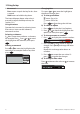
11 Gauges window The Gauges window shows boat data, such as water speed, as analog gauges. To select the Gauges window, press DISPLAY , select More, then select Gauges. Before using the Gauges window, set Speed range, Max RPM and Max fuel flow (see section 17-11). Selecting a Gauges layout The Gauges window can show one of four gauge layouts. To select a layout from the Gauges window, press MENU , select Layout and select a layout.
13 Fuel functions and display The Fuel functions require optional fuel sensors to be installed. 13-1 When you add or remove fuel When you add or remove fuel in a boat with no SmartCraft fuel tank level sensors, you must tell the Instrument, otherwise REMAINING, RANGE and the low fuel alarm will be meaningless. A When you completely fill the tank 1 Fill the tank. 2 Press SETUP then select Fuel. 3 Select Tank full.
13-2 Fuel window To go to the Fuel window, press DISPLAY , select Other, then select Fuel. The window is different if engine RPM is available (requires SmartCraft or diesel sensors to be installed): The Fuel window shows Used The fuel used during a trip. When you want to start measuring how much fuel is used, press SETUP , select Fuel and select Clear used. Remaining The amount of fuel remaining in the tank. Flow The fuel consumption per hour.
13-3 Fuel consumption curves A fuel consumption curve is a powerful tool for assessing your boat performance in different conditions and for helping you to run at the most economical speed for the conditions. Fuel consumption curves require engine RPM, which requires SmartCraft or diesel sensors to be installed. 13-3-1 Making a fuel consumption curve Making a fuel consumption curve requires running the boat in a straight line through the engine’s full RPM range for about 15 minutes.
13-3-2 Managing fuel consumption curves Record several curves for different conditions. Renaming a curve 1 Press SETUP then select Fuel. 2 Select Fuel consumption curve. Select Name, press ENTER and select the name of the curve to rename. 3 Select Rename and press ENTER . Change the name and press ENTER . Deleting a curve 1 Press MENU once or more until the Setup menu is displayed, then select Fuel. 2 Select Fuel consumption curve. Select Name, press ENTER and select the name of the curve to delete.
! CAUTION 14 Tides window The tides window! isWARNING available on Chart cards. The tides window shows tide information at a DANGER tide station for the selected date. CAUTION The tides window requires the local time offset to be set to work correctly (see section 14-11) To show the tides window for the tide station nearest to the boat, press DISPLAY , select Other, then select Tides. To go to the tides window for any tide station: 1 From the chart window, press MENU and select Find.
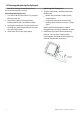
15 User card window A user card is an optional plug-in card that ! CAUTION can store data files (see section 1-3). There are three types of files: waypoints, routes or ! WARNING a track. To go to the user card window, press DISPLAY , select Other, thenDANGER select User card. CAUTION 1 Before using a user card, remove any chart card and plug the user card in. When you have finished with the user card, remove the user card and replace the chart card (see section 1-3).
To load a file to the Instrument: 1 Select the file to load. 2 Press MENU and select Load. Deleting a file from the user card 1 Select the file to delete. 2 Press MENU and select Delete. 3 Select Yes to confirm. Rereading the file information This reads the file names from the user card and displays them. Reading does not load any file data into the Instrument. You should not need to do this. 1 Press MENU and select Card. 2 Select Read. Formatting the user card Formatting prepares a user card for use.
16-1 The windows Distress Boats that have sent DSC distress messages and their positions. Poll Boats you have manually polled on the VHF radio, and their position at that time. Buddy track Buddy boats from your DSC radio. The radio regularly calls the boats and updates their positions. When your DSC radio receives a distress message, the Instrument creates a distress waypoint at the boat position. Distress waypoints have default names like DSTRSS01. The Instrument displays a Distress warning.
16-2 Using the windows Displaying a boat on the chart 1 Press or to select a boat. 2 Press MENU and select Display. The Instrument switches to chart window, with the selected boat position in the middle (see Boat positions above). B Going to a boat 1 Press or to select a boat. 2 Press MENU and select Goto. The Instrument starts navigating to the boat’s position (see Boat positions above). Creating a waypoint Polled and buddy track boats are not waypoints.
17 Setting up the 8120 The 8120 has a number of advanced features which are set up through the setup menu. We recommend that you become familiar with the operation of the unit using the default settings before making any changes in these menus. To go to a setup option menu, press SETUP to display the setup menu, then select an option. Note: 1 The Setup menu options are explained in the following sections. 2 Section 2-1 describes how to set or change data in the setup menus.
Setup option menus Factory default settings are shown. The setup data available will depend on the optional sensors and instruments installed.
17-1 Setup > System Press MENU once or more until the Setup menu is displayed, then select System: SmartCraft No SmartCraft gateway is fitted. Disable SmartCraft functions. SmartCraft gateway is fitted. Enable SmartCraft operation. See section 18-10. Buddy track Language Select the language for the windows. The options are: English, Italian, French, German, Spanish, Dutch, Swedish, Portuguese, Finnish and Greek.
17-2 Setup > Chart Press MENU once or more until the Setup menu is displayed, then select Chart: Palette Select the colour scheme for the LCD window. The options are: Normal Sunlight: Brighter colours, more visible in sunlight. Night: Reversed colours for night, to preserve night vision. Map datum Rotation The options for chart rotation are: North up: North is always at the top of the chart window. Track up: The chart is rotated so that the boat direction is to the top of the window.
NMEA datum offset If you select a map datum other than WGS 84, the map datum offset can be applied to latitude and longitude coordinates sent on the Instrument NMEA output: Latitude and longitude coordinates displayed on any NMEA repeater do not match the coordinates on the Instrument. Latitude and longitude coordinates broadcast on any NMEA VHF transmitter will be the same as the coordinates on a WGS 84 chart.
General submenu Plotter mode Only scales available on the chart card can be displayed. If you press or to select a chart scale which is not available, on the chart card, the chart window will change to this scale but will only display the boat position and track (if enabled). The rest of the window is white with black crosshatch lines and no chart information is displayed. This is useful to zoom to a small scale to track small boat movements or if there is no detailed chart for an area.
17-3 Setup > Sonar Press SETUP then select Sonar: Fish sensitivity Selects the minimum strength fish echo that will be displayed as a fish symbol. Higher values will display more fish symbols. Digit size Use this to remove or change the size of the depth window on the sonar windows. There is a choice of: Small, Medium and Large. Palette Frequency There is a choice of: 200 kHz, 50 kHz and Mixed. For information about selecting a suitable frequency for the water conditions, see section 8-3.
There is a choice of Auto, Short, Medium or Long. The Auto setting is recommended. Pulse power power output conserves the battery and produces a clear display in shallow water. There is a choice of Auto, Low, Medium or High. The Auto setting is recommended. This can be used to specify the power output of the transmitted ultrasonic pulse. Low 17-4 Setup > GPS Press MENU once or more until the Setup menu is displayed, then select GPS: erratic.
Clear Used Select Clear used to set Used (the amount of fuel used) to zero. Do this to start measuring how much fuel is used during a trip (see section 12-2 Used) Tank size Enter the capacity of the fuel tank. Navman recommends measuring tank size by draining the fuel tank, filling it to capacity and using the fuel dispenser’s reading. Beware of air pockets, especially in underfloor tanks. Num engines Set the number of engines to 0, 1 or 2. If 0 is selected the fuel features are turned off.
example vary the speed of one engine or have one engine running and the other stopped. 3 Press or to select the line with data for the port engine. Press ENTER . Press to select Port and press ENTER . 4 Repeat steps 2 and 3 for the starboard engine. 5 Press ESC when done. Water speed: Use paddlewheel sensor speed (boat speed through the water). This gives a more accurate value for Economy. GPS: Use GPS speed (boat speed relative to land). This gives a more accurate value for Range.
17-7 Setup > Logs Press SETUP then select Logs: The values can be reset independently of each other. These log values are saved when the unit is turned off. Reset trip dist This resets the trip distance to zero. Reset total dist This option resets the total distance to zero. Reset engine hours Use this option to reset the engine hours to zero. This can be useful after an engine service or to count the engine hours between service intervals.
Symbol Alarm Beeper Alarm sounds when it is on and the: Arrival radius boat is closer to the destination or to a waypoint than the alarm trigger value Anchor alarm boat moves by more than the alarm trigger value XTE boat moves off course by more than the CDI scale (see section 14-2) Danger boat comes closer to a danger waypoint than the alarm trigger value Too shallow 1 /5 sec depth is less than the alarm trigger value Too deep 1 /2 sec depth is greater than the alarm trigger value Fish
Note: that the units for wind speed are the speed units. Pressure Requires SmartCraft: kPa or psi Baro (Barometric pressure) Requires a Navman VHF receiver with barometer connected by NavBus: InHg or mB. 17-10 Setup > Comms Use this feature when the Instrument is connected to other NAVMAN instruments through NavBus or any compatible NMEA instrument.
Note: for accurate calibration: • The speed from a GPS receiver should be greater than 5 knots. • The speed from another paddlewheel transducer should be between 5 and 20 knots. • Best results are achieved in calm conditions where there is minimal current (best at high or low tide). Calibrating speed: 1 Travel at a constant, known speed. 2 In the Calibrate menu, select Speed. 3 Press or to change the displayed speed to the true value. 4 Press ENTER .
17-12 Setup > Time Press MENU once or more until the Setup menu is displayed, then select Time: 1 Select Local offset. 2 Press or to change the offset, then press ENTER . Time format The options are 24 hour or 12 hour. Date format Local offset The difference between local time and UTC (GMT). Change local offset when daylight saving time starts and ends. The range is 0 to ± 13 hours, in 30 minute steps. The options are dd/MMM/yy, MMM/dd/yy, dd/MM/yy or MM/dd/yy.
18 Installation ! CAUTION WARNING CAUTION Ensure that any holes cut are in a safe DANGER position and will weaken the boat’s ! not WARNING ! ! structure. If in doubt, consult a qualified boat builder. CAUTION DANGER CAUTION Do not mount any part where it can be used as a hand hold, where it might be submerged or where it will interfere with the operation, launching or retrieving of the boat. To help ensure proper operation, do not mount any part or cable within 0.
18-1 Installation: What else comes with my 8120? Navman GPS 1240 Antenna GPS 1240 Antenna bottom cone GPS 1240 Antenna gasket GPS 1240 mounting kit Sun cover for display unit Note: Place over display when not in use Front Bezel Note: Fit this after installing the display unit Power cable Mounting bracket and locking knobs Bracket mounting screws (5 x14 Gauge self tapping screws) Flush mounting screws (4 x 8 Gauge self tapping screws) Navman wallet Contains the following items: 71 • Flush mounting templa
18-2 Installation: Options and Accessories • Replacement paddle wheel. • C-MAP™ NT-MAX, NT+ or NT chart SD cards. • NAVMAN NavBus junction boxes simplify wiring, particularly if several instruments are connected. For more information, see the NavBus Installation Manual. Optional sensors and instruments External alarms: Lights or sounders in the boat to sound alarms through the boat (see section 18-4). GPS or DGPS antenna: For GPS navigation, see section 18-5.
Connections Sonar Video in Comms GPS Fuel/Nav Sonar Transducer Video Input (Analogue composite [NTSCPAL]) Not Used NAVMAN 1240 GPS Antenna - NAVMAN Fuel TXD - Diesel Fuel TXD - Smartcraft Gateway Not Used Power/data cable Wire Function Black Ground: power negative, NMEA ground (Connect both black wires to ground) Brown Not Used White NMEA out Blue NavBusRed Positive power in, 10 to 35 V DC Orange NavBus+ Yellow Auto power - Connect to red wire (positive power in) to enable A
There are two mounting arrangements: Flush Mounting the 8120 1. Attach the flush mounting template to the selected mounting position using adhesive tape. 2. Drill a pilot hole for each of the hole saw cuts shown on the template before cutting the larger hole with the hole saw. 3. Next cut all the way around the inside of the cut-out line with a saw to remove the waste material shown on the template. 4. Check that the unit fits correctly in the cut out area. Adjust the fit with a file if required. 5.
18-4 Installation: Power/data cable The power/data cable has a black locking collar and flying leads. 1 Wire the Instrument for auto power to have the Instrument turn on with the boat’s ignition switch or to record engine hours or if the Instrument must add up the total fuel used (for example if Navman petrol/gasoline fuel sensors are installed or if SmartCraft is installed without fuel tank level sensors). Otherwise wire for basic power (for more information, see section 2-2).
18-5 Installation: GPS antenna Selecting an antenna Fit one of these GPS antennas: • Normally use the GPS antenna supplied. • An optional differential beacon DGPS antenna to give enhanced accuracy within range of land based differential beacons in areas where WAAS or EGNOS are not available. Such a DGPS antenna has both a GPS receiver and a beacon receiver, and it automatically applies the beacon correction to the GPS position.
Blue Sonar cable Connect the transducer to the blue Instrument connector; tighten the locking collar. During setup a) set Sonar to (see section 17-1) b) set up the sonar options (see section 17-3) 18-7 Installation: Navman petrol/gasoline sensors Fit the optional petrol/gasoline fuel kit following the instructions supplied with the kit. Note: SmartCraft engines have fuel flow sensors, therefore Navman fuel sensors are not required as well. For dual engines, fit two kits.
18-9 Installation: DSC VHF radio Fit and set up the optional Navman DSC VHF radio following the instructions supplied with the radio. During setup: a) on the radio, enter buddy boats required b) on the Instrument, set NavBus to (see section 17-10) Black Power/data cable Orange Blue Radio power/data cable 18-10 Installation: SmartCraft If the boat has one or two SmartCraft capable Mercury petrol/gasoline engines, connect the Instrument to the SmartCraft engines with an optional SmartCraft gateway.
18-11 Installation: Other NavBus instruments NavBus is Navman’s system for connecting instruments together to interchage data and share transducers. When instruments are connected by NavBus: If the units, alarms or calibration are changed in one instrument, then the values will automatically change in all other instruments of the same type. Each instrument can be assigned to a group of instruments.
18-12 Installation: Other NMEA instruments NMEA is an industry standard for interconnecting instruments. It is not as flexible or as easy to install as NavBus. The Instrument can: Receive and display wind speed and direction from an optional compatible wind instrument. Receive and display depth, paddlewheel boat speed and water temperature from an optional compatible instrument. Receive data from an optional compatible GPS or GPS/DGPS source.
Appendix A - Specifications GENERAL Size: 256mm (10.08“) H x 385mm (15.16“) W x 78.5mm (3.09“) D. Allow 3mm clearance on each side for dust cover. Display: 307mm (12.1”) diagonal, TFT colour, 800 x 600 pixels. Backlight: Display and keys Supply voltage: 10.5 to 32 V DC. Supply current: at 13.8 V 350 mA min - no backlighting. 1A max - full backlighting. External beeper or light output: Switched to ground to sound alarm, 30 V DC, 200 mA maximum.
385 mm (15.1 ") List of datums 4m m (12 .1 256 mm (10.1 ") 30 78.5 mm(3.1 " ) ") 11.4 mm (0.45 ") Adindan American Samoa 1962 ARC 1950 Astro Beacon ‘E’ 1945 Astro Tern Island (Frig) 1961 Ayabelle Lighthouse Bissau Camp Area Astro Cape Chatham Island Astro 1971 Corrego Alegre Djakarta (Batavia) European 1950 Gan 1970 Guam 1963 Herat North Hong Kong 1963 Indian 1954 Indonesian 1974 ISTS 073 Astro 1969 Kerguelen Island 1949 L. C.
Appendix B - Troubleshooting This troubleshooting guide is written with the assumption that the user has read and understood the relevant sections in this manual. It is possible in many cases to solve difficulties without having to send the display unit back to the manufacturer for repair. Please follow this troubleshooting section before contacting the nearest NAVMAN dealer. There are no user serviceable parts.
B-2 GPS navigation problems 2-1 No GPS fix or long time to get fix at startup: a May occur occasionally if the antenna does not have a clear view of the sky. The satellite positions are constantly changing. b Antenna cable not connected to display unit. 2-2 Instrument GPS position different from true position by more than 10 m (33 ft): a Instrument in simulate mode. Turn simulate mode off (see section 17-14). b The normal error in GPS position will exceed 10 m (33 ft) for about 5% of the time.
3-2 Flow indicates no fuel or low fuel: a Check that the number of engines is set to 1 (see section 17-5). b Check that the fuel cable connectors are securely plugged in and the collar is locked in place. The collar must be locked in place to give a watertight connection. c A fuel transducer may be clogged. If so, remove the transducer from the fuel line and gently blow through it in the opposite direction to the fuel flow.
i Electrical noise from the boat’s engine or an accessory may be interfering with the transducer(s) and/or the Instrument. This may cause the Instrument to automatically decrease the Gain unless using Manual Gain. The Instrument thus eliminates weaker signals such as fish or even the bottom from the display. This may be checked by switching off other instruments, accessories (e.g. bilge pump) and the motor until the offending device is located.
Appendix C Glossary and navigation data Air temp - Air temperature (requires Navman 7200 VHF radio). Alarm status - Shows the symbol (see section 17-8) for each alarm that is on. The symbol is normally black and turns red if the alarm triggers. Attention Area - An important area on a chart, such as a restricted anchorage or a shallow area (see section 17-2). Bathymetric line - A depth contour line on the chart. Chart card - A plug-in card that stores chart data for a region (see section 1-3).
Navigation data The boat is sailing from the start to the destination and has moved off the plotted course from the start to the destination. BRG Bearing to Destination: Bearing to the destination from the boat. BRG Bearing to cursor: Bearing to cursor from boat (cursor mode, see section 3-2-1) CDI Course Deviation Indicator: When the boat is navigating to a point, the chart and highway windows show a parallel line on either side of the plotted course.
Appendix D Compliance statements FCC Statement Note: This equipment has been tested and found to comply with the limits for a Class B digital device, pursuant to Part 15 of the FCC Rules. These limits are designed to provide reasonable protection against harmful interference in a normal installation. This equipment generates, uses and can radiate radio frequency energy and, if not installed and used in accordance with the instructions, may cause harmful interference to radio communications.
Lon 174° 44.535’E Lat 36° 48.