High Rate 11Mbps Wireless Networking Access Point User’s Guide Rev. A1 December 2001 NWH650 National Datacomm Corporation 4F, No. 24-2, Industry East 4th Road, Science Park Hsin-Chu, Taiwan, R.O.C. Technical Support E-mail: techsupt@ndc.com.tw NDC World Wide Web www.ndc.com.
TRADEMARKS NDC and InstantWave are trademarks of National Datacomm Corporation. All other names mentioned in this document are trademarks/registered trademarks of their respective owners. NDC provides this document “as is”, without warranty of any kind, neither expressed nor implied, including, but not limited to, the particular purpose. NDC may make improvements and/or changes in this manual or in the product(s) and/or the program(s) described in this manual at any time.
Packing List The package should contain the following items: • One NWH650 InstantWave High Rate Access Point • One RS-232 Cable • One RJ-45 Cable • One Power Adapter • One CD ROM (Contains drivers, Station utilities, Access Point management tools, Network Profile Manager, User’s Guides, links to online resources InstantWave High Rate 11Mbps Access Point iii
Table of Contents INTRODUCTION ..................................................................................................1 INSTANTWAVE HIGH RATE FAMILY ......................................................................1 SYSTEM REQUIREMENTS .......................................................................................1 CABLING ...............................................................................................................1 HOW TO USE THIS GUIDE ............................
Config .............................................................................................................27 AP Settings......................................................................................................28 VIEWING INSTANTWAVE HIGH RATE INFORMATION AND STATISTICS ................40 View ................................................................................................................40 Saving the AP’s Configuration to a File..........................................
List of Figures FIGURE 1. SIMPLE WIRELESS INFRASTRUCTURE NETWORK ....................................3 FIGURE 2. SINGLE AP NETWORK ............................................................................4 FIGURE 3. MULTIPLE AP NETWORK ........................................................................4 FIGURE 4. ACCESS POINT ........................................................................................8 FIGURE 5. ACCESS POINT LEDS ..........................................................
Introduction Congratulations on choosing one of NDC’s InstantWave High Rate wireless networking products. InstantWave High Rate was one of the first IEEE 802.11b wireless standard compliant products in the industry and was designed to maximize the convenience of networking. You will find InstantWave High Rate products very easy to setup and use. The User’s Guide gives comprehensive instructions on installing and using the InstantWave NWH650 High Rate Access Point (AP).
How to Use this Guide InstantWave High Rate is extremely versatile in providing varying levels of network management. For Small Office/Home Office users, setup and configuration is a quick, four-step process. The Access Point Hardware Installation section, on page 8, provides simple instructions to get your network up and running within minutes.
Planning Your Network Infrastructure Network Types An Infrastructure network is formed by several stations and one or more Access Points (APs), with the stations within a set distance from the AP. Figure 1 depicts a typical Infrastructure network topology. There are three infrastructure network setups that are commonly used. It is a good idea to understand the possible network setups and configuration requirements before planning your wireless network. Type 1.
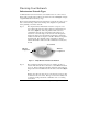
Server Wired Computers Access Point Wireless Computers Figure 2. Single AP Network Type 3. The third type of network is composed of multiple APs and multiple Stations (Figure 3). Server “Sales” Domain Wireless Cell A AP-1 Wireless Cell B AP-3 AP-2 Station -1 Wireless Cell C Station -2 Station -3 Figure 3. Multiple AP Network The reasons for having multiple APs installed are: 1. 2.
Planning an Infrastructure Network This section explains some of the things you need to consider in planning an Infrastructure network. Setting up is a two step process. 1. 2. Install and configure the InstantWave High Rate products Decide the best physical location of the InstantWave High Rate products so as to optimize performance The following sections give quick guidelines for these two steps.
Roaming InstantWave High Rate products are equipped with seamless roaming capabilities. Roaming is necessary to prevent mobile Stations from being disconnected from the network as they move around. InstantWave High Rate is designed to allow wireless Stations to roam freely within an infrastructure domain composed of multiple APs with overlapping signal coverage (as in the Type-3 network configuration described in the previous section).
Access Point Placement Guidelines A characteristic of radio communication is the interference problem. Radio is receptive to interference. Therefore, the more interference you can avoid, the better performance you will get from wireless products. The following section describes how the InstantWave High Rate AP should be placed to reduce possible interference. A few tips to mention that are particularly significant in a radio wave communications system: 1.
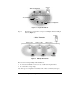
Getting Started Access Point Hardware Installation Access Point Hardware Setup explains how to quickly setup the Access Point for use via a wired Ethernet connection, and using the factory default settings. For installation in networks using other than the default settings, i.e. into existing networks, complete the Hardware Setup and refer to Using the AP COMFig Tool, page 11. To setup a wireless station, refer to the PCI/PC Card User’s Guide. Figure 4. Access Point step1.
General Color Red Function Unlit: Power OFF Blinking: Diagnostic test On: Healthy condition On: Abnormal Condition PWR (Power/Status) Green E/N (Ethernet) Color Function TX/RX Orange LINK Green Blinks to indicate Ethernet transmission/reception activity Indicates an Ethernet link. If the radio fails, this LED will not light RF Color Function TX/RX Orange LINK Green Blinks to indicate radio transmission/ reception activity Indicates a wireless link.
Hardware Pre-Configuration Before adding an AP into an existing Ethernet network, you may need to set basic configurations, e.g. domain name (SSID), security setting (WEP), AP name, channel number, or IP address in order to make it compatible with the existing network. Follow the steps below to connect the AP to a PC for configuration: step1. Connect the supplied RS-232 cable to the COM port on the AP and connect the other end to a serial port (COM port) on the PC step2.
Using the AP COMFig Tool The AP COMFig Tool is a Windows based utility used to configure the AP via a COM port connection between the AP and a PC. It provides the following functions: • Sets AP parameters (e.g., IP address, Domain name (SSID), Security, etc.) • Diagnoses the AP hardware and shows the diagnostic results • Upgrades the AP firmware • Resets the AP Configuration • Manages the APMS Host table To start the AP COMFIG Tool, click Start/Programs/InstantWave High Rate AP/AP COMFig Tool.
Figure 8. AP COMFig Tool/Password AP COMFig/Service After connecting with the AP, click on the Service tab to open the Service card (Figure 9). The Service card provides access to the management features. Figure 9. AP COMFig Tool/Service Click the View and Modify AP Configuration button. The Configuration screen will open (Figure 10).
General: The General card (Figure 10) is the first card in the Configuration section. Figure 10.
On this card, you can set and view general AP settings: AP Alias Name Assigns the AP a unique human friendly name that allows the AP to be easily identified Domain Name (SSID) This is commonly called the Domain Name but is defined in the IEEE 802.11b Wireless Standard as SSID.
Regulatory Domain Identifies the country where the AP is used. Each country has defined its available channel numbers and transmission power (see Appendix, page 52) BSSID This is the MAC ID of the AP Firmware Version The current AP firmware version Important: In a multiple cell network topology, overlapping and/or adjacent cells using different channels can operate simultaneously without interference if the frequency distance between the center frequencies is at least 30MHz.
Figure 11. Configuration/Encryption The dropdown Method box lists three options: 1. Disabled (default) - Disable data encryption 2. 40-bit WEP - Enable use of 40-bit WEP 3. 128-bit WEP - Enable use of 128-bit WEP Key Generation - There are two ways to generate a security key. The first is by entering any text in the Passphrase field. Click the Generate button. For 40-bit WEP, it will generate four keys, Key 1, Key 2, Key 3, and Key 4. Select a key number from the dropdown list of the Default Key box.
IP: Note: These SNMP related settings are only useful for network management and remote configuration (APMS). For proper wireless connections, these settings don’t have to be changed. From the IP card (Figure 12) you may view or modify the Access Point’s TCP/IP address, configure its subnet mask, or add a default gateway (see the note below). Note: An AP will directly transfer SNMP respond packets (confirmation packets) to an APMS PC if it is within the same LAN (the same subnet mask).
Figure 12. Configuration/IP After making any changes, click the Apply button to make the changes effective immediately, without closing the dialog box, or click OK to accept the changes and close the box. Note: Click Add to APMS Host Table to add the configured AP to the APMS Host Table.
Filter: The next tab on the dialog box is Filter (Figure 13). This is a one-way protocol filtering mechanism that prevents the AP from transmitting specified protocols from a wired Ethernet LAN into the wireless LAN. If you do not require particular protocols on the wireless part of your network, you can save bandwidth by enabling the protocol filter. Figure 13.
SNMP Access Control: SNMP Access Control is the next tab on the box (Figure 14). Figure 14. Configuration/SNMP Access Control The AP’s access control is managed by a control table on the AP. The first time this box is opened, the table will be empty. This means that there are no restrictions on who can access and reconfigure the AP and any user may modify the AP’s operation. To avoid chaos on the network, access to the AP configuration should be restricted to only those for whom it is necessary.
Figure 15. New Entry Two levels of access are available. Read Read-only rights. The user may read everything except the Access Control settings, but cannot alter anything Read/Write The user may read and alter all settings Enter your IP address and then set your own access rights to Read/Write (see the following note). Note: Do not set all the stations in the Access Control table to Read. Once this is set and enabled, it will be difficult to modify the AP.
Figure 16. Hardware Diagnosis Click Start and the tests will commence. As each item is tested, a yellow arrow will appear alongside it. If the test is successful, the arrow will change to a green tick. If a failure occurs, an “X” will appear. You can click Cancel at any time to stop the tests. When the tests have completed, the Cancel button changes to a Close button. Click Close to return to the Service card.
Figure 17. Upgrade AP Firmware Use the Browse button to choose the file to be uploaded to the AP, or type the file location and name in the File Name field. The Upload button will then become enabled. Click Upload. The new firmware will be loaded into the AP’s flash memory area. When the file transfer is complete, click OK to begin the AP’s internal firmware updating process.
Figure 19. APMS Table-1 From here you can view/delete all the APs added to this host table. This table can be saved and retrieved from the APMS utility so that you don’t need to create such a table again in the APMS utility. Select an AP in the table and click the Details button to view and edit it’s SNMP access control settings (Figure 20). Figure 20. APMS Table-2 After making any changes, click OK to return to the Service card.
Using the Access Point Management System (Advanced Configuration and Management) Once the AP is connected to an Ethernet network, a network administrator can connect to it from any PC on the same network via the Access Point Management System (APMS) utility. The APMS utility is a Windows-based SNMP management tool, allowing network administrators to remotely configure and monitor APs through an Ethernet or wireless connection.
Figure 22. Network Management System-2 2. Click the AP main menu item to open its sub-menu and then click Create New AP (Figure 23). Figure 23. Network Management System-3 Input the AP’s IP address and its community string (this string will be used for SNMP access control). When the information has been entered, the OK button will become active. Click OK. Repeat the process to add more APs. To delete an AP icon from the window, first select it and then press the Delete key.
Figure 24. AP Properties Here you may modify the IP address and Community string. Changes made here will be immediately effective. If the connection attempt was unsuccessful, a message box will appear informing you that the request had no response. Click OK to close the message box and return to the main screen. Go through the procedure again to retry.
The menu offers configuration options that enable you to tailor your network to suit your needs. • AP Settings - sets the AP’s IP related parameters, sets filters, sets wireless related parameters, sets AP Access Control list • Trap Management • Load Factory Configuration • Upgrade AP Firmware • Reset AP AP Settings Click AP Settings to open the AP Settings dialog box (Figure 26). Figure 26.
LAN, then the SNMP respond packet needs to go through a router-gateway. The default gateway is the path to that router. If you set the correct default gateway, then you can use a PC running APMS located on a different subnet to manage this AP. All InstantWave Access Points are delivered with a default IP of 192.168.1.1 and a default subnet mask of 255.255.255.0. If you wish to change the defaults, set each AP to its new IP address before introducing it to the open network.
From the Filter card, some, all, or none of the protocols listed may be selected for filtering out: • IP protocol • IPX protocol • NetBEUI protocol • AppleTalk protocol • Other protocols • Internet Multicast Frames Selecting a protocol to be filtered will activate the AP’s protocol filtering immediately on clicking OK. Clicking Reset AP is not required.
Private Transfer: TFTP currently has no provisions for user authentication. We suggest you keep the ‘Private Transfer’ option checked in order to prevent anyone other than the network administrator using the APMS program to upgrade the AP firmware. If you want to use a third party TFTP tool to upgrade the AP firmware, this option should be disabled. Timeout: Specifies the number of seconds TFTP waits to make sure that the sender has completed the transmission. The range is from 3 to 255 seconds.
Note: Do not set all the stations in the Access Control table to Read. Once this is set and enabled, it will be difficult to modify the AP. Should this situation occur, use the AP COMFig utility to re-set the configuration. Two levels of access are available. To set access rights, enter a station’s IP address and community string (the community string must be the same as the AP’s in the Host Table of the APMS manager terminal, i.e. the PC running APMS) and choose Read or Read/Write. Read Read-only rights.
Access Options MAC Address List: Status Disables or enables an individual entry Address The MAC address of a wireless station Comment A brief description of the wireless station Access Options: Disabled Stops MAC access control, all wireless stations are allowed to associate with this access point Accepted List The station will be rejected if its MAC address IS NOT in the list Denied List The station will be rejected if its MAC address IS in the list New: Click New to create a new entry in the M
Wireless: Clicking on the Wireless tab opens the wireless card (Figure 31). Figure 31.
The Wireless card groups all the user configurable wireless Access Point (AP) functions. Here you may make settings as follows: AP Alias Name Domain Name (SSID) Assigns the AP a unique name Secure SSID • Blocks a connection request without the exact SSID • Hides the SSID in outgoing beacon frames. A site survey tool will not find the AP This is more commonly called the Domain Name but is defined in the IEEE 802.11 Wireless Standard as SSID.
Encryption: Note: Most wireless connection problems arise from improper WEP settings so make sure all APs and wireless stations use the same settings. Sets the data encryption parameters for the wireless LAN. Click the arrow to the right of the Method box. The dropdown list has three options: Figure 32. AP Setting/Encryption Disabled (default) Stations communicate with this Access Point without any data encryption. 40-bit WEP Stations communicate with this Access Point via 40-bit WEP data encryption.
The first is by entering any text in the Passphrase field. Click the Generate button. For 40-bit WEP, it will generate four keys, Key 1, Key 2, Key 3, and Key 4. Select a key number from the dropdown list of the Default Key box. If you do not select a key, key 1 is selected, as it is the default key. For 128-bit WEP, only one key is generated. Click OK. Another WEP key generation method is to insert the key values directly from the keyboard. Enter your own key into one of the Key 1~4 fields.
Figure 34. AP Trap Server Program When the AP is powered on, or an Ethernet port becomes active, an event log will be generated indicating the time, the MAC ID of the reporting AP, and the activity. You may save, open, and delete log files from the File menu. In the Program menu, select Auto Startup After Reboot to activate the Trap Server when the system is rebooted, or Pause Program to pause the Trap Server. Load Factory Configuration Clicking Load Factory Configuration opens a dialog box.
Figure 35. Upgrade AP Firmware The Upload button will then become enabled. Click Upload to start uploading the file to the Access Point. The APMS and the AP’s built-in Trivial File Transfer Protocol (TFTP) command will upload the new executable into the AP’s flash memory area. If the upload activity fails, an error message will be shown on the message box. Resetting the AP will take about 30 seconds.
Viewing InstantWave High Rate Information and Statistics View The menu items under View provide read-only information and statistics. To customize the screen view, right-click in the main screen to open a context sensitive menu. Select your preferred view, i.e. Icons, List, Details, etc. Figure 36. View Menu The Status bar at the bottom of the screen shows the connecting status. When the bar shows Ready, Associated will appear on the bar along with the IP address of the associated AP.
Figure 37. AP Information When finished viewing AP information, click OK to close the window. Wireless Stations The Connected Wireless Stations window lists all the currently associated wireless station’s Media Access Control (MAC) addresses. When finished viewing, click OK to close the window. Statistics Clicking statistics opens a sub-menu with two options: Wireless Port and Ethernet Port. A list of Tx and Rx statistics data follows.
Figure 38. Wireless Port Statistics Figure 39. Ethernet Port Statistics These statistics will be lost when the Access Point (AP) reboots or is reset. To poll for new statistics click on the Polling Timer button. Set the time period (in seconds) and click OK to close the box. Click Update to start the polling sequence. The statistics shown may be saved to a file or printed. Click OK to return to the main menu.
Figure 40. Save AP Configuration Loading the AP’s Configuration from a File To load a configuration file (.WLN) to the Access Point, on the File menu, click Load AP Configuration. Select a configuration file and open it. The following dialog box will open and display the detailed settings. Figure 41. Load Configuration Include IP address settings: If you want to include the IP settings, check this option (overwrites the AP’s current IP settings).
attributes of security keys are externally write-only and cannot be saved into the configuration file. Click Encryption to setup the security keys manually. Password Clicking Password opens a Change Password configuration box. Enter your new password and then enter it again to confirm. Click OK to close the box. Once a password is set you will be asked for it each time the APMS program is opened. Note: The password is shared between the APMS and the AP COMFig program on the same PC.
Troubleshooting This section provides you with some troubleshooting info should you encounter installation or operation problems on InstantWave High Rate products. If the problems still cannot be remedied after going through the Troubleshooting section, check the FAQs at http://www.ndc.com.tw/support/tech/iw_faq.htm If you still have a problem, contact NDC technical support for assistance (see Technical Support, page 47).
A wireless PC cannot associate with the AP, even though the link quality is perfect and the taskbar indicator is green. Make sure your wireless PC is using a WiFi compliant adapter and has the same SSID and security settings as the AP. 1. SSID: The ‘Domain Name (SSID)’ is case-sensitive and must be the same as that of the AP. See Figure 10, page 13 (AP COMFig) or Figure 31, page 34 (APMS). 2.
Technical Support Support from Your Network Supplier If assistance is required, call your supplier for help. Have the following information ready before you make the call. 1. LED status 2. A list of the product hardware (including revision levels), and a brief description of the network structure 3. Details of recent configuration changes, if applicable Support from NDC If you have any problems that you cannot resolve with the information in troubleshooting, or the FAQs at http://www.ndc.com.
NDC Limited Warranty Hardware NDC warrants its products to be free of defects in workmanship and materials, under normal use and service, for a period of 12 months from the date of purchase from NDC or its Authorized Reseller, and for the period of time specified in the documentation supplied with each product.
3. Charges: Usually RMA (Returned Material Authorization) items will be returned to the purchaser via airmail, prepaid by NDC. If returned by another carrier, the purchaser will pay the difference. A return freight and handling fee will be charged to the purchaser if NDC determines that there was “No Problem Found” or that the damage was caused by the user. Warning NDC is not responsible for the integrity of any data on storage equipment (hard drives, tape drives, floppy diskettes, etc.).
Specifications General Regulatory Compliance Standards FCC Part 15 Class B. (US) Data Rate 11Mbps/5.5Mbps/2 Mbps/1Mbps auto fallback Communication Method Security Half-Duplex LED Indicators Power, Ethernet Activity, Ethernet Link, Wireless Activity, Wireless Link Interfaces/Connectors 10Base-T: RJ-45 RS-232C: V.24 compliance. D-SUB 9 pin Power Power Voltage: DC 5.1Volt ± 5 % AC Adapter: AC 100V~240V Power Consumption: 5.1Volt, 1.0 A (Typical) Dimensions 138 x 114 x 37mm (5.43 x 4.49 x 1.
Software SNMP Functions Configuration via COM port and Configuration and management via SNMP in a Windows environment through Ethernet.
Appendix This appendix lists the channels supported by the world’s regulatory domains. The channel numbers, channel center frequencies, and regulatory domains are shown in the table.
EC DECLARATION OF CONFORMITY For the following equipment: Product Name : InstantWave Wireless Access Point Model Number : NWH650 is hereby confirmed to comply with the requirements set out in the Council Directive on the Approximation of the Laws of the Member States relating to R&TTE Directive(99/ 5/ EC). For the evaluation regarding the electromagnetic compatibility, the following standards were applied.
Index A Accepted List ................................ 33 Access Control........................ 20, 31 Access Options ............................. 33 Access Rights ......................... 20, 31 Alias Name ............................. 14, 35 AP COMFig Password ................................... 11 Service ...................................... 12 AP COMFig Tool Using......................................... 11 AP Configuration Load .......................................... 43 Save ...................
Polling Timer ................................ 42 Properties ...................................... 26 Protocol Filtering .................... 19, 29 R Regulatory Domains ............... 15, 35 Reset AP Configuration ................ 23 Resetting the AP ........................... 39 S Save AP Configuration ................. 42 Secure SSID............................ 14, 35 Self Diagnostic Test...................... 21 Service Set ID ......................... 14, 35 Service/AP COMFig.....................