
User's Manual


ND-70185 (E) CHAPTER 4
Page 35
Revision 3.0
INSTALLATION
Key Setting on Circuit Cards
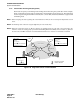
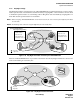
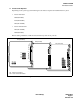
2.3 PA-24DTR (DTI)
There are two types of the PA-24DTR (DTI) card as shown below. Refer to Figure 4-6 and Table 4-4 to set
each switch to the proper positions.
Figure 4-6 Switch Locations on DTI (PA-24DTR) Card
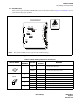
Table 4-4 Switch Setting Patterns for the DTI Card
SWITCH NAME
SWITCH
NUMBER
SETTING
STANDARD
SETTING
MEANING
MB
UP Circuit card make busy
DOWN × Circuit card make busy cancel
SW13B
0
ON Internal Loopback: Set
OFF × Internal Loopback: Cancel
1
ON External Loopback: Set
OFF × External Loopback: Cancel
2
ON Payload Loopback: Set
OFF × Payload Loopback: Cancel
3
ON All Channel Make Busy: Set Note
OFF × All Channel Make Busy: Cancel
Note:
Dots printed in DIP switches represent the standard settings.
1
234
OFF
1234
OFF
12345678
OFF
1
2345
6
78
OFF
12345678
OFF
1
234
56
7
OFF
1234
OFF
1234
OFF
1234567 8
OFF
1234 5678
OFF
12345678
OFF
1234567 8
OFF
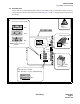
SW4D SW5D
SW6C
SW39
SW58
SW25
OPE
N-OPE
MB
SW13B
PCM
FRM
BER
RMT
AIS
BL23
BL00
CN2
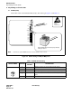
ATTENTION
Contents
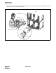
Static Sensitive
Handling
Precautions Required
DTI (PA-24DTR) Card
0
1
2
3