
Single-Chip Microcontrollers User's Manual


185
CHAPTER 8 16-BIT TIMER/EVENT COUNTER
ES31 ES30 ES21 ES20 ES11 ES10 0 0
76543210Symbol
INTM0
FFECH 00H R/W
Address After Reset R/W
ES11
INTP0 Valid Edge Selection
ES10
0
Falling edge
0
0
Rising edge
1
1
Setting prohibited
0
1
Both falling and rising edges
1
ES21
INTP1 Valid Edge Selection
ES20
0
Falling edge
0
0
Rising edge
1
1
Setting prohibited
0
1
Both falling and rising edges
1
ES31
INTP2 Valid Edge Selection
ES30
0
Falling edge
0
0
Rising edge
1
1
Setting prohibited
0
1
Both falling and rising edges
1
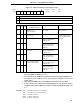
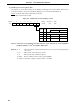
(6) External interrupt mode register 0 (INTM0)
This register is used to set INTP0 to INTP2 valid edges.
INTM0 is set with an 8-bit memory manipulation instruction.
RESET input sets INTM0 value to 00H.
Figure 8-8. External Interrupt Mode Register 0 Format
Caution Before setting the valid edge of the INTP0/TI00/P00 pin, stop the timer operation by clearing bits
1 through 3 (TMC01 through TMC03) of the 16-bit timer mode control register (TMC0) to 0, 0, 0.