
Single-Chip Microcontrollers User's Manual


217
CHAPTER 9 8-BIT TIMER/EVENT COUNTERS
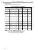
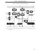
Figure 9-1. 8-Bit Timer/Event Counter Block Diagram
Note Refer to Figures 9-2 and 9-3 for details of 8-bit timer/event counters 1 and 2 output control circuits 1 and
2, respectively.
8-Bit Compare
Register 10 (CR10)
Match
8-Bit Timer
Register 1 (TM1)
Selector
Clear
Selector
Selector
f
XX
/2-f
XX
/2
9
f
XX
/2
11
TI1/P33
f
XX
/2-f
XX
/2
9
f
XX
/2
11
TI2/P34
4
TCL
17
TCL
16
TCL
15
TCL
14
TCL
13
TCL
12
TCL
11
TCL
10
Timer Clock
Select Register 1
8-Bit Timer Mode
Control Register
TMC12 TCE2 TCE1
Internal Bus
LVS2 LVR2
TOC
15
TOE2 LVS1 LVR1
TOC
11
TOE1
4
8-Bit Timer
Register 2 (TM2)
8-Bit Timer/
Event Counter
Output Control
Circuit 1
8-Bit Timer Output
Control Register
8-Bit Timer/
Event Counter
Output Control
Circuit 2
Clear
Match
8-Bit Compare
Register 20 (CR20)
Selector
Note
Note
INTTM1
TO2/P32
INTTM2
TO1/P31
4
4
Selector
Internal Bus