
Single-Chip Microcontrollers User's Manual


268
CHAPTER 14 A/D CONVERTER
ES71
7
ES70
6
ES61 ES60
4
ES51
3210
FFEDH
Address
INTM1
Symbol
ES50 ES41 ES40
5
00H
After
Reset
R/W
R/W
ES41
0
0
1
1
ES40
0
1
0
1
Falling edge
Rising edge
Setting prohibited
Both falling and rising edges
ES51
0
0
1
1
ES50
0
1
0
1
Falling edge
Rising edge
Setting prohibited
Both falling and rising edges
ES61
0
0
1
1
ES60
0
1
0
1
Falling edge
Rising edge
Setting prohibited
Both falling and rising edges
ES71
0
0
1
1
ES70
0
1
0
1
Falling edge
Rising edge
Setting prohibited
Both falling and rising edges
INTP3 Valid Edge Selection
INTP4 Valid Edge Selection
INTP5 Valid Edge Selection
INTP6 Valid Edge Selection
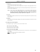
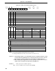
(3) External interrupt mode register 1 (INTM1)
This register sets the valid edge for INTP3 to INTP6.
INTM1 is set with an 8-bit memory manipulation instruction.
RESET input sets INTM1 to 00H.
Figure 14-4. External Interrupt Mode Register 1 Format