
Single-Chip Microcontrollers User's Manual


307
CHAPTER 16 SERIAL INTERFACE CHANNEL 0 (
µ
PD78058F SUBSERIES)
(2) SBI definition
The SBI serial data format and the signals to be used are defined as follows.
Serial data to be transferred with SBI consists of three kinds of data: “address”, “command”, and “data”.
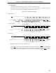
Figure 16-11 shows the address, command, and data transfer timings.
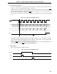
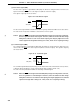
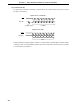
Figure 16-11. SBI Transfer Timings
Remark The dotted line indicates READY status.
The bus release signal and the command signal are output by the master device. BUSY is output by the slave
signal. ACK can be output by either the master or slave device (normally, the 8-bit data receiver outputs).
Serial clocks continue to be output by the master device from 8-bit data transfer start to BUSY reset.
SCK0
SB0 (SB1)
SCK0
SB0 (SB1)
SCK0
SB0 (SB1)
89
9
A7 A0 ACK BUSY
C7 C0 ACK BUSY READY
89
D7 D0 ACK BUSY READY
Address Transfer
Command Transfer
Data Transfer
Bus Release
Signal
Command Signal
Address
Command
Data