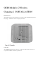
OEM M Modu M ule( (Wiireleess Chaarginng) INS STA ALLA ATIION INTRODU UCTION This bullletin discuusses the installatiion procedure for the t OEM Module((Wireless Chargingg) – Indivvidual wirreless chaarging traansmitter. OVERVIE EW The OEM M Module(Wirelesss Chargiing) – Ind dividual dual-mode d e transmitter is compliannt with PM MA and WPC W Qi sstandardss.
The transmitter is tuned for best performance through 8 mm (0.315") of Corian® solid surface. Instructions for optimum placement and installation are in this bulletin. Due to the precise routing required the installation should be done in the fabrication shop prior to sheet installation. The OEM Module(Wireless Charging) – Individual package consists of the transmitter, power cord and transformer.
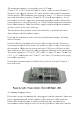
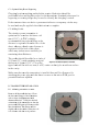
The transmitter reequires a rectangullar space of 82 mm mx 92 mm (3.23"x 3..60") belo ow the surrface cou unter. Allo ow an exttra 25 mm m (1") distance to any suupport stru ucture. N No metal should s be betweenn the transsmitter and the ssurface. The T transm mitter alsoo requiress 36 mm (1 7/16") vvertical clearance measuredd from thhe top surfface (24 m mm (0.94 4") from bottom b suurface).
with the area. Subtle or temporary markings may be more appropriate where there are a limited number of users that will become familiar with the location over time. Marking options include laser engraving or inlays for permanent marks, and stickers for temporary marks. Laser engraving will leave a slight depression and may be more difficult to clean. For high visibility markings choose a contrasting color. In commercial environments this may incorporate corporate color logos.
C.1. Optioonal Inlay/L Laser Engrraving Chargingg locationn marking g methodss that requ uire fabriication shhould be performeed before milling the t pockeet for the transmitte t er. Standaard techniques for engravinng or creaating inlay ys may bee used to identify the t chargiing locatiion. If the cusstomer dooes not deesire a peermanent indicator a temporrary sticker may be used aand may be b applied when fa fabrication n is comp plete. C.2.
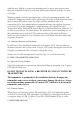
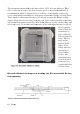
The transmitter iss attached d to the shheet with a 100% silicone s addhesive. Place P dabs of ssilicone at each of the four ccorners. Clear C or trranslucennt adhesiv ve is recommeended, whhite is sho own here for visibility. Avo oid highlyy contrastting colors, pparticularlly dark ad dhesive w with more transluceent, lighteer- coloreed sheets. There neeeds to bee enough silicone tto fill the gap betw ween the fl flange and d the surface. Keep the silicone away from m the coiil.
The transmitter is supplied with a power cord consisting of DC and AC wiring connected with a transformer. In many cases an AC power outlet may need to be installed in the cabinetry where the transmitter is to be installed. Local codes must be followed and the AC outlet often must be installed by a licensed electrician. The adapter shall be installed near the equipment and shall be easily accessible. E. LED INDICATOR The LED will indicate the current transmitter status. F.
Hereby, Neosen Energy LLC declares that this device is in compliance with the essential requirements and other relevant provisions of Directive 1999/5/EC. Notice: Observe the national local regulations in the location where the device is to be used. This device may be restricted for use in some or all member states of the European Union (EU) FCC STATEMENT 1. This device complies with Part 15 of the FCC Rules.