
User Manual

© 2013 by Net Optics, Inc. Net Optics® is a registered trademark of Net Optics, Inc. Director™ and Director Pro™ are trademark of Net Optics, Inc. 800-0038-002 Rev. E 09/13
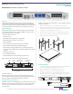
Rack Mount the Director Device
Director is designed for rack mounting in a 19-inch equipment rack and
occupies one rack unit.
1. Expand the mounting rails to t the depth of your rack. See (A).
2. Attach the mounting rails to the front and rear pillars of the rack using
the supplied screws. The rail shelves that the Director chassis will sit on
should be located along the bottom of the rails.
3. Slide the chassis into the rack so it rests on the rail shelves. See (B).
4. Fasten the chassis with the supplied screws at the front panel ears.
5. Make sure the rack is properly grounded.
19.0
23.73
1.72
(A)
(B)
Rail shelves along bottom
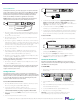
Connect to AC Power
1. Install a power supply cord restraint clip over it to keep the AC power
cord from unplugging from the AC power connector.
2. Connect an AC power cord to the AC power connectors.
3. Plug the other end of the cord into an AC power circuit.
4. For redundant power, connect the other AC power cord to the other
AC power connector on the rear panel and plug the other end of the
cord into a dierent AC power source.
1 0 1 0
USB
3 4
10G
Management Port
Console Port
AC Models
Independent Power Sources
Introduction
This document provides the initial steps to congure both the Director
and Director Pro appliances. For more information on the two appliances,
refer to the Director User Guide and Director Web Guide located on the CD.
In this guide, both Director and Director Pro are referred to as Director.
Unpack and Inspect
Carefully unpack Director and review the following components. Retain
the packing material for later use. Contact Net Optics customer service if
any component is missing or damaged.
• Director or Director Pro unit
• Two Power cords
• Two Cables, 3 Meter, RJ45, CAT 5e 4-pair (purple)
• Cable, RJ45-DB9, for console port connection
• Rack mounting Kit
• Two 10-32 x 5/8” screws and washers (for rack mounting)
• Director and Director Pro Quick Install Guide (this guide)
• CD containing the Director and Director Pro User Guide, Director and
Director Pro CLI Command Reference, and Director and Director Pro Web UI
User Guide
• Registration instructions
• Service Plan Reference Guide
• Extended Warranty, if an extended warranty is purchased
XFP and SFP modules are ordered and shipped separately.
www.netoptics.com
™
Director
2
1
1 2 54
6 7 8
10
9
1 2
10G
1
2
Monitor
LASER
CAUTION!
Span
10
100
1000
LINK
ACT
1 2 3 4 5 6
7 8 9
10 11 12
In-Line
A
A
B
B
A
A
B
B
A
A
B
B
1 2 3
4 5 6
10 SFP
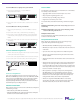
Monitor
Ports
2 XFP
Configurable
10GbE Ports
2 Director Network Module (DNM) Slots
DNM with 10/100/1000
Copper Network Ports
(6 In-line or 12 Span Ports)
DNM with SX Fiber
Network Ports
(6 In-line or 12 Span Ports)
Monitor PortsPower LEDs
Network Ports
DIR-7400 Model
Plan the Installation
Determine an IP address to assign to the device Management port. If
you access Director through a gateway, determine the network gateway
address and subnet mask before beginning the installation.
Restricted Access Location (RAL)
Net Optics recommends installing Director in a Restricted Access Location
(RAL) for locations with unreliable earthing or for customers with security
concerns, since only trained service personnel can access equipment
located in a RAL.
Version 7.6
Quick Install Guide
Director™ Data Monitoring Switch
Director Pro™ Network Controller Switch