
User Manual

© 2013 by Net Optics, Inc. Net Optics® is a registered trademark of Net Optics, Inc. Director™ and Director Pro™ are trademark of Net Optics, Inc. 800-0038-002 Rev. E 09/13
Computer with terminal
emulation software
Cisco DB9 to RJ45
Console Cable
1 0 1 0
Management
Port
Console
Port
10G
5. Set the Director IP address by typing: sysip set ipaddr=<ipaddress>
mask=<netmask> gw=<gateway> sysip commit where <ip
address> is the IP address for Director, <netmask> is the netmask, and
<gateway> is the IP address of the gateway
6. For more information on the CLI, type Help to display command
information, or see the CLI Reference manual.
7. Use Tab to auto-complete partially typed commands. Enter ? following a
command (and a space) displays the arguments for that command.
The up- and down-arrow keys access the CLI command history buer.
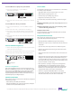
To access via SSH:
1. Connect the Management port with a CAT 5e cable to a switch/hub.
To network switch or hub
4
1 0 1 0
Management
Port
Console
Port
10G
2. In a terminal window of a PC connected to the network, at the
prompt, type: ssh admin@<IP_address>.
3. Enter the password, netoptics. The Net Optics banner displays.
4. Log into Director with the default username admin and password
netoptics if no other accounts have been added.
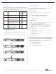
Connect to the Network
If the Director Network Modules (DNMs) are not already installed
when you receive the unit, install them by sliding them carefully into
the DNM slots in the front panel.
To install DNMs:
1. Remove the cover plate from Slot 1 (if present) by unscrewing the two
thumbscrews.
www.netoptics.com
1
2
B
A
A B
www.netoptics.com
™
Director
2
1
1 2 54
6 7 8
10
9
1 2
10G
1
2
Monitor
LASER
CAUTION!
Span
10
100
1000
LINK
ACT
1 2 3 4 5 6
7 8 9
10 11 12
In-Line
10
100
1000
LINK
ACT
A
A
B
B
A
A
B
B
A
A
B
B
1 2 3
4 5 6
Slot 1
Slot 2
2. Slide the DNM into Slot 1 with the DNM circuit boards riding in the
rails.
3. Push in the DNM rmly until you feel the connectors mate and the
bezel is ush with the front panel.
4. Secure the DNM with the two captured thumbscrews.
5. Repeat for Slot 2 if installing two DNMs.
Warning! Use caution when installing the DNM into the chassis
to prevent damage to any components on the bottom side.
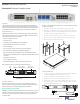
Connect to DC Power
For DC powered models, you must supply your own power cables. DC
power cables must have a wire gauge of at least 16 AWG and a 72 VDC,
6A rating. You need a Phillips screwdriver to complete installation. If
present, remove the protective covers from the DC power terminal
blocks. Use the Phillips screwdriver to tighten the connections.
Caution: Always connect the earth electrical grounds rst, and keep the
earth grounds connected whenever you are working on the device.
For use with -48V Only
-
+
For use with -48V Only
-
+
Management
Port
Console
Port
10G
1 0 1 0
Management
Port
Console
Port
10G
Earth
Ground
-48VDC
Return
-48VDC
Return
Power Source 1
Power Source 2
Independent Power Sources
1. Connect an earth ground lead to the terminal labeled with the ground
symbol ( ), which is the left-most terminal, on both DC power terminal
blocks on the rear of the chassis.
2. Connect Power Source 1 DC power cables to the DC power terminal
blocks on the rear panel.
3. Connect the negative (– 48VDC) side of the cable to a terminal labeled
with the minus symbol (–), and the positive (0V) side of the cable to the
terminal labeled with the plus symbol (+). The negative (minus symbol)
terminal is in the center, and the plus terminal is to the right.
4. Connect Power Source 2 DC power cables to the DC power terminal
blocks on the rear panel.
5. Connect the negative (– 48VDC) side of the cable to the terminal
labeled with the minus symbol (–), and the positive (0V) side of the
cable to the terminal labeled with the plus symbol (+).
6. Carefully connect the other two – 48VDC ends of the DC power cables
to two negative (– 48VDC) power sources.
Caution: If possible, turn o the power to the power sources while you
are making the following connections.
7. Connect the other two + 48VDC ends of the DC power cables to two
positive (+ 48VDC) power sources.
Note: Be sure to connect the positive side of a cable to the positive side
of the power source, and the negative side of the power cable to the
negative side of the power source.
Congure Director
All conguration options, status, and statistics are congurable and
viewable using the command-line interface (CLI). To get started with the
Director, connect a console to the Director device console port interface
to access the CLI. Through the local CLI, set the Management port IP
address to enable remote access to the device.
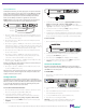
To access the Command Line Interface:
1. Connect a PC with terminal emulation software to the Director device
Console port using the supplied DB9 to RJ45 cable.
2. Launch the terminal emulation software such as
HyperTerminal or minicom and set the communication parameters:
115200 baud, 8 data bits, no parity, 1 stop bit, no ow control.
3. At the login prompt, type admin, and at the password prompt, type
netoptics.
4. Enter a new password for the admin account.