
User Manual

© 2013 by Net Optics, Inc. Net Optics® is a registered trademark of Net Optics, Inc. Director™ and Director Pro™ are trademark of Net Optics, Inc. 800-0038-002 Rev. E 09/13
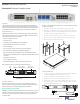
To connect Director to a Span port on your network:
1. Connect any network port on a Span DNM to an
appropriate network cable.
www.netoptics.com
™
Director
2
1
1 2 54
6 7 8
10
9
1 2
10G
1
2
Monitor
LASER
CAUTION!
Span
10
100
1000
LINK
ACT
10
100
1000
LINK
ACT
1 2 3 4 5 6
7 8 9
10 11 12
In-Line
A
A
B
B
A
A
B
B
A
A
B
B
1 2 3
4 5 6
To Span port
2. Connect the other end of the cable to a Span port on a network
switch.
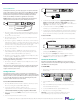
To connect Director in-line to your network:
1. Connect any “A” network port on an in-line DNM to a network
cable.
2. Connect the other end to a network link you are tapping.
3. Connect the corresponding “B” network port to an appropriate
network cable. In-line port pairs are located side-by-side in the
DNMs.
4. Connect the other end to the other side of the network link you
are tapping.
www.netoptics.com
™
Director
2
1
1 2 54
6 7 8
10
9
1 2
10G
1
2
Monitor
LASER
CAUTION!
Span
10
100
1000
LINK
ACT
10
100
1000
LINK
ACT
1 2 3 4 5 6
7 8 9
10 11 12
In-Line
A
A
B
B
A
A
B
B
A
A
B
B
1 2 3
4 5 6
To network switch A To network switch B
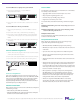
Connect to Monitoring Devices
1. Remove the temporary plug from the monitor slot and insert the
SFP module until it clicks into place.
2. Connect the cable supplied with the SFP module to the SFP port.
3. Connect the other end of the cable to the monitoring device.
www.netoptics.com
™
Director
2
1
1 2 54
6 7 8
10
9
1 2
10G
1
2
Monitor
LASER
CAUTION!
Span
10
100
1000
LINK
ACT
1 2 3 4 5 6
7 8 9
10 11 12
In-Line
10
100
1000
LINK
ACT
A
A
B
B
A
A
B
B
A
A
B
B
1 2 3
4 5 6
To monitoring device
Connect to 10 Gigabit Ports
Each of the 10 Gigabit ports (two on the front of the chassis of
DIR-7400 and DIR-6400p, and two on the rear of DIR-7400 and DIR-
5400, one rear port for DIR-6400p), can be connected as network
or monitor ports. These ports require XFP modules (ordered and
shipped separately). The function of the port, as network or monitor, is
determined by how you congure the port.
Check the Installation
After you have made your connections to the Director, verify that it
is functioning correctly:
• Check that the power LEDs are illuminated.
• Check the link LEDs for each of the connected ports to verify that
the links are connected and trac is present.
Create a Filter
To view trac on monitor ports, you must dene one or more lters.
For example, create a lter that:
• Aggregates trac received on network ports 1 to 5 and 7
• Drops any trac originating from 10.1.1.1
• Forwards only Layer 4 trac going to Port 80
• Regenerates it to monitor ports 1 and 2
To create the lter, enter the three following commands using the
CLI:
Net Optics> lter add in_ports=n1.1-n1.5,n1.7 ip4_src=10.1.1.1
action=drop
Net Optics> lter add in_ports=n1.1-n1.5,n1.7 l4_dst_port=80
action=redir redir_ports=m.1-m.2
Net Optics> lter commit
For more information, see the Director and Director Pro User Guide
included on the Director CD.
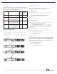
Daisy Chain Director Units
Daisy chaining (or stacking) is the process of creating a single,
logical multi-unit system from many systems.
• DIR-7400, DIR-5400 and DIR-6400p support daisy chaining.
• DIR-6400p can only be used as a master unit and/or the slave unit
of the chain.
• Up to ten units can be daisy chained in one multi-unit system.
• All units in the system must be running the same version of the
Director software.
• All units must have their own IP address and be connected to the
network.
• All units must be interconnected in a daisy chain conguration by
cabling port t2.2 (rear right 10G port) of the Master unit to port
t2.1 (rear left 10G port) on the next unit. Ports t2.1 on the rst unit
in the daisy chain and t2.2 in the last unit are unused (they cannot
be used as network or monitor ports.)
• Once systems are operating in a daisy chain, all management
(CLI, Web Manager, and System Manager) functions operate
through the master unit. If a remote unit’s device management
functions are accessed through the remote unit’s serial port or
management IP address, the results are unpredictable.
• All units are assigned Unit ID (UID) numbers consecutively
starting with 1. The UID 1 is at the beginning of the daisy chain
and is the master unit; the rest are slave or remote units.