User Guide NB9, NB9W ADSL2+ VoIP Modem Router
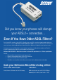
Did you know your phones will disrupt your ADSL2+ connection... Even If You Have Older ADSL Filters? Due to faster ADSL speeds, an inline ADSL2+ Microfilter stops your ADSL connection being disrupted by telephones connected to the same line. Older filters cannot handle these speeds. A high-quality Microfilter from NetComm will ensure you have a stable broadband Internet connection with no reduction in the quality of your telephone service.
Contents Overview...................................................................................................................................................... 5 NB9/NB9W Package Contents................................................................................................................. 6 Selected terminology used in this manual................................................................................................. 6 Do I need a micro filter?....................................
Save & Reboot................................................................................................................................ 51 Advanced.............................................................................................................................................. 52 Advanced > WAN........................................................................................................................... 52 Advanced > LAN..........................................................
Overview Thank you for purchasing the NetComm NB9/NB9W ADSL2+ VoIP Router. NetComm is proud to introduce this entirely new class of all-in-one device incorporating ADSL2+, VoIP and Wireless in a single compact unit. The NB9/NB9W is truly a ‘broadband communications gateway’ that, when attached to the appropriate ISP services, will enable multiple broadband communications streams to run concurrently into your home or office.
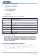
NB9/NB9W Package Contents Your NB9/NB9W contains the following items: • NB9 or NB9W ADSL2+ Modem Router • 15VDC 1.
Minimum System Requirements: Different aspects of the NB9/NB9W have different requirements, so let’s look at them in turn. We’ll start with your computer, which ought to match the following requirements if you are to enjoy the benefits of a highspeed ADSL connection and use of VoIP and Wireless Networking. PC Requirements: • Any computer running Windows 98/2000/Me/XP/Vista or Macintosh OSX • Ethernet or Wireless Network card • CD-ROM drive • Web browser e.g. • Internet Explorer 5.
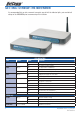
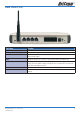
Getting to Know the NB9/NB9W It is recommended that you take a moment to acquaint yourself with the indicator lights, ports and default settings of the NB9/NB9W prior to commencing with installation.
Back Panel Ports Port Name Function WLAN ACC (for NB9W only) WLAN Access Control. Antenna (for NB9W only) Wireless LAN antenna. 4 x LAN 4 x 10/100 Base-T Ethernet jack (RJ-45) to connect to your Ethernet Network card or Ethernet Hub / Switch. ADSL Telephone jack (RJ-11) to connect to your Telephone Wall Socket (ADSL line).
Default Settings The following are the default LAN (Local Area Network) and WAN (Wide Area Network). LAN (Management) • Static IP Address: 192.168.1.1; • Subnet Mask: 255.255.255.
Connecting the NB9/NB9W Follow the steps in this section to configure ADSL, VoIP, Wireless, only one, or any combination of these. The diagram below shows you how to connect the NB9/NB9W to your PC, ADSL and POTS service.
1. Connecting the Cables Note: If you wish to link to the NB9W wirelessly at the outset, see Establishing a Wireless Connection below. 1. Connect your PC using Ethernet cable to one of the LAN ports of your NB9/NB9W; 2. Connect the POTS pass-through line ; i. Connect telephone wall-socket to port on in-line splitter called LINE; ii. Connect one end of an RJ11 (telephone) cable to PHONE port of the in-line splitter and connect the other end to the LINE port on NB9/NB9W; 3.
2. Establishing an ADSL connection via PPPoE Having physically connected your NB9/NB9W, the next step is to establish your ADSL connection to the Internet, via your ISP. Nearly all Australian ISPs connect their clients via a standard method called PPPoE (Point-to-Point Protocol over Ethernet). Your NB9/NB9W has a ‘Quick Setup’ page configured for easy access via PPPoE, so all you need to do is enter the Username and Password issued by your ISP, click the ‘Save & Reboot’ button and connection will follow.
4. Enter your PPPoE Username and PPPoE Password and click the Save & Reboot. The NB9/NB9W will apply all of the settings in approximately 2 minutes. 5. After several minutes, you should then see the Basic>Home page indicating your ADSL service is connected. Proceed to configure VoIP and Wireless, if required.
3. Establishing your Wireless Connection (for NB9W only) Wireless networking provides an alternative connection to using Ethernet cable. Wireless access is enabled by default on your NB9W with the following default settings: • Wireless network name (SSID): ‘wireless’; • Security: WEP (64-bit) HEX key: ‘a1b2c3d4e5’; Note: For advanced wireless settings of your NB9W refer to the User Guide included on your NB9/NB9W CD ROM.
4. Setting up your VoIP account Once you have successfully connected to the Internet you are ready to setup your VoIP account to start making telephone calls over the Internet. This section will deal with setting up a single VoIP account with standard settings. Note: Make sure you get all your necessary VoIP account details from your VSP (VoIP Service Provider) before you begin. These details are not your ADSL User Name and Password.
3. Interface Name: Don’t change the ‘Interface name’ setting; 4. Priority Codec: The priority codec is set to ‘G729’ which means your NB9/NB9W will firstly choose this codec when communicating with your SIP proxy from your VSP (VoIP Service Provider); 5. Ptime: The ‘ptime’ is the time delay (milliseconds) between voice packets sent. Do not change this value unless your VSP has asked you to; 6. SIP Proxy: Check the ‘use SIP proxy’ checkbox the enter the SIP Proxy IP address (issued by your VSP); 7.
Computer Hardware Configuration This section provides instructions for configuring the TCP/IP (Network) settingson your computer to work with your Modem. These steps are only required if you are having trouble accessing your Modem. Windows® XP PCs 1. In the Windows task bar, click the Start button, and then click Control Panel. 2. Click on Network & Internet Connections icon. (Category mode only). 3. Click the Network Connections icon. 4.
Windows 95, 98 PCs First, check for the IP protocol and, if necessary, install it: 1. In the Windows task bar, click the Start button, point to Settings, and then click Control Panel. 2. Double-click the Network icon. 3. The Network dialog box displays with a list of currently installed network components. If the list includes TCP/IP, and then the protocol has already been enabled. Skip to step 9. 4.
Digging Deeper – Advanced Settings Your NB9/NB9W has many advanced features that you may want or need to use in the future. Let’s start by taking a look at the menus in the web interface. 1. Login to the NB9/NB9W web interface (http://192.168.1.1); 2. Enter your username & password (default is ‘admin’ / ‘admin’); The NB9/NB9W has the following main menu items: • Basic • Voice • Wireless (NB9W only) • Management • Advanced • Status Let’s explore these menus in detail.
Basic Basic>Home The first page you see after you have successfully setup your NB9/NB9W is the Basic > Home which provides a summary of the status of your NB9/NB9W: Field Description Uptime System: Uptime status for various connections. Software Version The current version of software (firmware) loaded into your NB9/NB9W Bootloader (CPE) Version The version of the bootloader Wireless Driver Version The version of the wireless driver Line Rate – Upstream The upstream line rate in Kbps (e.g.
Basic>ADSL Quick Setup The NB9/NB9W web configuration page can be opened in a Web Browser window of a computer attached to the device by entering the Web address http://192.168.1.1. Enter User ID: admin and password: admin. The ‘ADSL Quick Setup’ page will then be displayed when the device is first started, or if you have deleted your WAN connection settings or reset the NB9/NB9W to factory defaults.
Voice About SIP & VoIP Voice Settings The NB9/NB9W has the ability to connect two regular telephones via the Phone1 and Phone2 ports on the rear of the unit and provides a number of sophisticated call-management functions such as call forward, call waiting, call transfer and so on. The following section provides further details of how to set up VoIP services, and then how to use the advanced telephony functions offered by the NB9/NB9W.
Voice Menu 1 Enter your VoIP details in the NB9/NB9W through the Voice menu. Clicking on the Voice Menu will retrieve the following screen: Entries in these fields are as follows: Field Value Interface name Current WAN connection; if you have set up your PPPoE connection to your ISP, this will display the current WAN connection. Preferred codec Value recommended by your VSP; default is G.729. Preferred ptime Value recommended by your VSP; default is 20.
Voice Menu 2 The lower part of the Voice entries screen provides fields in which details of your VoIP telephone number(s) are entered, along with several other VoIP parameters. The NB9/NB9W provides for two telephone ‘extensions’. If you have one VoIP number and one telephone handset, plug this phone into Port 1 and enter the VoIP details in fields labelled with 1… . If you have two handsets and one VoIP number then enter the same details in fields 1. and 2., above.
Field Means Enable Phone 1 call waiting. To enable Call waiting feature on Phone 1. Enable Phone 2 call waiting. To enable Call waiting feature on Phone 2. Call forward Type:. To enable call forward on phone1 and 2. Calls to the account will be forwarded to the nominated phone number in “Call Forward Phone Number” field. Signaling and Media QoS. Leave as default unless instructed by your VoIP Service Provider.
Voice > Dial Plan The NB9W supports two types of Dial Plan. Outgoing Dial Plan works for both VoIP and PSTN connection and Incoming Dial Plan that only works for VoIP connection. Click on their respective link on the menu to access the configuration page. Voice > Dial Plan > Outgoing Click the Add button to add a new Outgoing Dial Plan Rule. Voice > Dial Plan > Incoming Click the Add button to add a new Incoming Dial Plan Rule.
Voice > Dial Plan > Advance This feature allows you to set advance Dial Plan. Click the Add button to add a new rule. Priority: The value can be ranged from 0-32767. The lower number is the higher priority. Each call will be checked gradually according to the priority, once the call meets one of the rule, it will stop checking and take the action.
Wireless (NB9W only) Wireless Setup The NB9W serves as an 802.11g Wireless Access Point, with enhanced capabilities provided by Broadcom’s XPressTM technology. The first screen in the Wireless menus is as follows: Field Enter Enable Wireless Check Enable Wireless to turn on wireless transmission Hide Access Point If this is checked, wireless clients will need to know the SSID (=wireless network name) if they wish to join the network.
Wireless Security Quick Setup Security settings are used to prevent unauthorised connection to your network. This can be as basic as a neighbouring user who detects and is able to connect through your wireless network, right through to actual malicious interference or ‘hacking’.
Quick Security Setup 2 – WPA-PSK If a stronger network security settings is required, go to Wireless>Security and select WPA-PSK from the Network Authentication drop-down menu. Enter a network key of your choice in the WPA Pre-Shared Key field; this can be from 8 to 63 characters and contain special characters and spaced. And change the WPA Group Rekey Interval to 3600. Select TKIP for WPA Encryption and leave WEP Encryption as disabled.
Wireless Security in Detail The following provides a detailed summary of wireless terms and acronyms and more in-depth explanations of the topic. It assumes little prior knowledge of wireless networking and is aimed at providing background for the terminology used in the NB9W Wireless Security screens.
WEP and WPA “WEP” stands for Wired Equivalent Privacy and was the original wireless security method. Over time it was found to be vulnerable to attacks based on de-coding the ‘keys’ used to encrypt the data.
WPA WPA requires a RADIUS server to provide client authentication. WPA also requires specification of the ‘WPA Group Rekey Interval’ which is the rate that the RADIUS server sends a new Group Key out to all clients. The Re-Keying process is part of WPA’s enhanced security. This method also requires specification of the IP address of a RADIUS server, the port on which to connect to the RADIUS server, and the shared key used to authenticate with the RADIUS server.
WPA2 ‘WPA Pre-authentication’ support in WPA2 allows a client to pre-authenticate with the NB9W toward which it is moving, while maintaining a connection to the access point it’s moving away from. This new capability allows the roaming to occur in less than 1/10th of a second while a traditional roam without PMK caching and pre-authentication would take more than one second. Time-sensitive applications like Citrix, video, or VoIP will all break without fast roaming.
Wireless Configuration To enter advanced settings for the wireless network hosted by the NB9W, click on Wireless > Configuration: Many of these fields may not need to be altered and may require interpretation by a network engineer.
Fragmentation Threshold Enter a value between 256 (min) and 2346 (max). A threshold, specified in bytes, that determines whether packets will be fragmented and at what size. On an 802.11 WLAN, packets that exceed the fragmentation threshold are fragmented, i.e., split into smaller units suitable for the circuit size. Packets smaller than the specified fragmentation threshold value are not fragmented. If you experience a high packet error rate, try to slightly increase your ‘Fragmentation Threshold’.
Wireless > Mac Filter The Wireless > MAC Filter page displays the following: This function allows wireless access to be restricted or allowed based on the MAC address of the client device. When MAC address filtering is set to “Allow”, access to the wireless is allowed only to the clients that are listed in the list. When set to “Deny”, access to the wireless is restricted only to the clients that are listed in the list.
Wireless > Bridge Wireless bridge mode is used to provide a wireless link between WLAN segments to provide greater coverage or to extend network size and reach. If a wireless router is used in bridge mode, then Access Point functionality is disabled. Network Bridges operate to ‘bridge’ two network segments on the ‘physical’ or MAC link layer. This section describes how to configure the NB9W in bridge mode.
Management Management > Device Settings > Backup Backup enables you to save a copy of the NB9/NB9W configuration file. This can be re-loaded to restore your settings should you need to reset the device to its factory defaults. Click on “Backup Settings” button to start the backup process. The default file name is backupsettings.conf, or give it an explanatory name (e.g. NB9WHome.conf) and save it to somewhere safe on your computer. Click on “Backup Settings” button to start the backup process.
Management > Device Settings > Update Firmware The ‘Update Firmware’ screen allows you to obtain an updated firmware image file from NetComm. Manual software upgrades from a locally stored file can be uploaded using this screen by selecting a firmware file saved to your hard-disk and clicking the ‘Update Firmware’ button. Notes: Please make sure that any firewall or anti virus program is turn off before updating the firmware.
Management > SNTP The SNTP option under Management menu configures the NB9/NB9W’s time automatically by synchronizing with Internet time servers. Note: The NB9/NB9W is configured to Australian EST by default. Tick the corresponding box displayed on the screen. Then click Save/Apply. Access Control > Services The Services Option limits or enables selective access via the LAN or WAN via the following services: Enable the service by checking the corresponding box and clicking SAVE/APPLY.
Access Control > IP Addresses The IP Addresses option limits the Access>Services by IP address. If the Access Control Mode is enabled, only the listed IP addresses can access the NB9/NB9W for the specified services. Before the service is enabled, specify the IP addresses by clicking the Add button and entering the address details. Enter the IP address and click Apply to allow access. Access Control > Password This page allows you to change the password for all users account.
Advanced Advanced > WAN Clicking on the ‘Advanced’ menu displays the following: This screen provides a summary of the current WAN interfaces you have configured. If you have connected the NB9/NB9W to ADSL through the ADSL Quick Setup interface, details of the connection will be summarised here. Setting up a WAN profile goes through a set of steps which establishes connection parameters covering the following: Field Means VPI/VCI Always 8/35 in Australia Con. ID Sequence number of connection (e.g.
Alternative Connection Types (Inc PPPoA) In the event that you wish to set up an alternative connection type, for example a PPPoA connection rather than the more common PPPoE type, this is done in the following screen which is accessed from Advanced>WAN>New. Select required connection type, click on Next and follow the prompts.
Advanced > LAN Configure the NB9/NB9W’s LAN IP address and subnet mask. Save button only saves the LAN configuration data. Save/Reboot button saves the LAN configuration data and reboots the NB9/NB9W to make the new configuration effective. Field Means LAN IP Address Default: 192.168.1.1. The LAN IP address of your NB9/NB9W. LAN Subnet Mask Default: 255.255.255.0. The subnet mask of your NB9/NB9W. A subnet mask is used to determine what subnet an IP address belongs to.
Enable IGMP Snooping IGMP specifies how a host can register a router in order to receive specific multicast traffic. IGMP Snooping allows the NB9/NB9W to capture IGMP frames. When your NB9/NB9W hears an IGMP report from a host for a given multicast group it adds the host’s port number for that group. When the NB9/NB9W hears an IGMP Leave, it removes the host’s port from the table entry.
Advanced > NAT > Explanation NAT stands for Network Address Translation, a process which converts private IP addresses of a computer on the internal private network to one or more public IP addresses for the Internet. NAT changes the packet headers to the new address and keeps track of each session; when packets come back from the Internet, it performs the reverse conversion to the IP address of the client machine.
Advanced > NAT > Port Forwarding Note: This option is not available if your NB9/NB9W is in Bridge mode. To display the NAT function, you need to have enabled the NAT feature in the WAN Setup. By default, NAT is enabled on your NB9/NB9W Clicking on Advanced > NAT displays the following: The Port Forwarding feature allows you to direct incoming traffic from WAN side (identified by Protocol and External port) to the internal server with private IP address on the LAN side.
If you are setting up a common server (e.g FTP) you can select the type of server from the dropdown list. Selecting the server will automatically configure the necessary ports. For custom service, you need to enter the External Port Start and External Port End for the service. Enter the Server’s IP address (e.g. 192.168.1.110) Click ‘Save / Apply’ Let’s take a detail look at the fields on this page. Field Means Select a Service Select a type of service you wish to host on your LAN.
Advanced > NAT > Port Triggering Port triggering is similar to Port Forwarding however where port forwarding is tied to a specific IP address, Port triggering is dynamic and is tied to a particular application event request. The ‘Custom Application’ settings, or the pre-sets that are provided by the application names in the drop-down menu, allows specific ports to be opened by the named applications.
Advanced > NAT > DMZ A DMZ Host PC is set up ‘between’ your (private) LAN and the (public) WAN to allow access from the outside world to a specified and isolated zone on your network. It is most commonly used to provide access to a Web server or Game server without exposing the rest of your computers to the Internet. Enter the IP address of the DMZ computer and click ‘Save/Apply’.
Advanced > Security > IP Filtering IP filtering allows you to deny or permit any packet from passing through the modem explicitly. You can set either incoming filtering or outgoing filtering. Outgoing means the data is transferred from your computer onto the internet while Incoming means the data is transferred from outside onto your computer. Notes: By default, all outgoing traffic is allowed and all incoming traffic is blocked. However they can be change accordingly by setting up filters.
Advanced > Security > Parental Control Parental Control allows NB9/NB9W administrator to restrict access according to hours of the day. To add a new rule click on the Add button and the following page will appear. Enter target machine’s MAC address and create a Rule Name (called ‘User Name’) and a time range.
Advanced > QoS Quality of Service offers a defined level of performance in a data communications system - for example the ability to guarantee that voice traffic is given priority over other network traffic to ensure that conversations are not disrupted by other network requirements. This means that should you be talking via the VoIP facility and someone else in the house starts downloading a big file, the download won’t disrupt the flow of voice data.
For example, to set up QoS for VoIP traffic for the NB9W you need to set it according to the screenshot below: 56 NB9/NB9W ADSL2+ VoIP Router YML790 Rev8
Advanced > Routing > Default Gateway Default Gateway is checked by default and ensures that the NB9/NB9W will accept the first received IP address assigned to it by the DHCP server to which it connects. This will generally be the ISP’s server. You would only uncheck this if the NB9/NB9W was being used in Static Routing mode (see below).
Advanced > Routing > Static Route Static routing allows computers that are connected to the NB9/NB9W to communicate with computers on another LAN segment which are connected to the NB9/NB9W via another router. See diagram below for example setup: To set a static route, click add and enter the relevant details in the fields e.g. 192.168.1.
Advanced > Routing > Dynamic Route Dynamic routing makes use of the RIP protocol to allow the NB9/NB9W to adapt to changes in the network. RIP enables the device to determine the best route for each packet based on the ‘hop count’ or number of hops between Source and Destination. Advanced > DNS > DNS Server This page allows user to enable automatic DNS from the ISP or specify their own DNS server address manually.
Advanced > DNS > Dynamic DNS Dynamic DNS allows users to create a static hostname for their dynamic IP address. This service will allow easier access to the DSL router from the internet. In order to use this service, you need to register with the service provider such as DDNS.org or TZO. Click the Add button to add a dynamic DNS. Advanced > DSL This page allows user to modify the DSL modulation settings on the unit.
Status Status > Diagnostics Self explanatory. A series of indicators about various parameters of your broadband connection. Use to troubleshoot connection problems; in event of a fail signifier, click on Help and follow troubleshooting instructions. Note the Ping Default Gateway is an optional parameter and fail may not affect connection. Status > System Log Click on View System Log to view entries or on “Configure System Log” to set parameters for log entries.
Status > Statistics Display the statistics for LAN, WAN, ATM and ADSL connection. Applicable to network or device engineers and administrators. Status > WAN Displays summary of current WAN connection including your ‘Public’ WAN IP (last cell in display). Status > Route Summarises parameters of IP route for device. Status > ARP Display the ARP table on the device.
Status > DHCP Provides summary of DHCP leases provisioned by NB9/NB9W. Useful source to find client machine MAC addresses. Status > Bridging Display the bridging information on the device. Status > IGMP Proxy Display the IGMP Proxy table.
Appendix A: Troubleshooting Problems with LAN PCs on the LAN cannot get IP addresses from the ADSL Router. The chances are that the interface used as DHCP server is modified and the client PCs does not renew IP addresses. If your DHCP server is enabled on Private IP Address previously and you modify the interface to Public IP Address, the client PCs should renew IP addresses. The PC on the LAN cannot access the Web page of the ADSL Router. Check that your PC is on the same subnet with the ADSL Router.
Problem with Wireless Windows can not configure this wireless connection (Windows XP). Enable Wireless Zero Configuration by following these steps: 1. Click on the Start Menu. Click on Run, type in “services.msc” (without the quotes). Press OK. 2. Scroll down to the bottom of the list, locate the service named Wireless Zero Configuration and doubleclick on it. 3. Change the Startup type to Automatic and check the “Service status”. 4.
Appendix B: Establishing your wireless connection (for NB9W only) The following examples use the default wireless configuration. Windows XP service pack 2 Follow these steps: 1. Open Network Connections (Start > Control Panel > Network Connections): 2. Right-click on your Wireless Network Connection and select View Available Wireless Networks: 3.
4. Enter the network key (default network key is “A1B2C3D4E5”) and click Connect: 5. The connection will show Connected.
Mac OSX 10.4 Follow these steps: 1. Click on the Airport icon on the top right menu. 2. Click on the network name that you want to connect. The default wireless network name is “wireless”. 3. On the new window, tick on Show Password and type in the network key in the Password field. The default network key is “A1B2C3D4E5”. After that, click on OK. 4. To check the connection, click on the Airport icon and there should be a tick on the wireless name.
Windows Vista Follow these steps: 1. Open Network and Sharing Center (Start > Control Panel > Network and Sharing center). 2. Click on “Connect to a network”.
3. Choose “Connect to the Internet” and click on “Next”. 4. Choose “Wireless”.
5. Click on the wireless network name. In this example, the wireless network name is “wireless” and click “Connect”. The default wireless network name is “wireless”. If you have not change the wireless network name, please click on “wireless”. 6. Tick on “Display Characters” and type in the network key. The default network key is “A1B2C3D4E5” and this example use the default key. Click “Next” after that.
7. Select the appropriate location. This will affect the firewall settings on the computer. 8. Tick on both “Save this network” and “Start this connection automatically” and click on “Next”.
9. Now the connection is ready. Notes: For other operating system such as Windows 98SE, Windows ME and Windows 2000 or if you use the wireless adaptor utility to configure your wireless connection, please consult the wireless adaptor documentation respectively.
Appendix C: How to change Wireless Security on your NB9W WEP encryption The NB9W has the WEP encryption enabled by default. To change the encryption key, please follow the following steps: 1. Connect the computer directly to the modem using Ethernet cable. 2. Open the web configuration, http://192.168.1.1/ from your web browser i.e. Internet explorer, Firefox. 3. At the log in screen, enter the Username and password. The default Username is “admin” and the default Password is “admin”. Then click on “Login”.
WPA encryption When a more secure connection is needed, you can change the wireless security settings on the NB9W to WPAPSK. Please follow the following steps: 1. Connect the computer directly to the modem using Ethernet cable. 2. Open the web configuration, http://192.168.1.1/ from your web browser i.e. Internet explorer, Firefox. 3. At the log in screen, enter the Username and password. The default Username is “admin” and the default Password is “admin”. Then click on “Login”. 4.
Appendix D: Glossary 10BASE-T A designation for the type of wiring used by Ethernet networks with a data rate of 10 Mbps. Also known as Category 3 (CAT 3) wiring. See also data rate, Ethernet. 100BASE-T A designation for the type of wiring used by Ethernet networks with a data rate of 100 Mbps. Also known as Category 5 (CAT 5) wiring. See also data rate, Ethernet. ADSL Asymmetric Digital Subscriber Line. The most commonly deployed type of DSL for home users.
DSL Digital Subscriber Line A technology that allows both digital data and analog voice signals to travel over existing copper telephone lines. Ethernet The most commonly installed computer network technology, usually using twisted pair wiring. Ethernet data rates are 10 Mbps and 100 Mbps. See also BASE-T,100BASE-T, twisted pair. Filtering To screen out selected types of data, based on filtering rules. Filtering can be applied in one direction (upstream or downstream), or in both directions.
Microfilter In splitterless deployments, a microfilter is a device that removes the data frequencies in the DSL signal, so that telephone users do not experience interference (noise) from the data signals. Microfilter types include in-line (installs between phone and jack) and wall-mount (telephone jack with built-in microfilter). See also splitterless.
splitterless A type of DSL installation where no splitter is installed, saving the cost of a service call by the telephone company. Instead, each jack in the home carries both voice and data, requiring a microfilter for each telephone to prevent interference from the data signal. ADSL is usually splitterless; if you are unsure if your installation has a splitter, ask your DSL provider. See also splitter, microfilter. subnet A subnet is a portion of a network.
Appendix F: Registration and Warranty Information All NetComm Limited (“NetComm”) products have a standard 12 month warranty from date of purchase against defects in manufacturing and that the products will operate in accordance with the specifications outlined in the User Guide. However some products have an extended warranty option (please refer to your packaging).
Product Warranty The warranty is granted on the following conditions: 1. This warranty extends to the original purchaser (you) and is not transferable; 2. This warranty shall not apply to software programs, batteries, power supplies, cables or other accessories supplied in or with the product; 3. The customer complies with all of the terms of any relevant agreement with NetComm and any other reasonable requirements of NetComm including producing such evidence of purchase as NetComm may require; 4.
NB9/NB9W ADSL2+ VoIP Router YML790 Rev8
Want to network your home quickly and easily without any hassles? NetComm HomePlugs are the simplest method available to set up a home network, without any of the hassle of laying meters of cable or drilling holes into walls. Simply put, a NetComm HomePlug turns the existing electrical wiring in your home into a network capable of transmitting data at up to 200Mbps. Setting up a network couldn’t be easier.
Product Warranty NetComm products have a standard 12 months warranty from date of purchase. However some products have an extended warranty option, via registering your product online at the NetComm website www.netcomm.com.au. Refer to the User Guide for complete product warranty conditions, limitations of warranty and other legal and regulatory information. Contact Information If you have any technical difficulties with your product, please do not hesitate to contact NetComm’s Customer Support Department.