Start Here Congratulations on your purchase of the NETGEAR™ Model EN516 or Model EN524 Ethernet hub. These hubs deliver standards-based, plug-and-play networking solutions for small businesses, home offices, and low-density workgroups of larger companies.
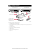
Package Contents Model EN516 hub Model EN524 hub or EN516 EN524 MODEL 16PORT 10/100Mbps Ethernet Hub 1 BNC Rx 10/100Mbps 9 Ethernet Hub 1 5 Link/Rx Partition Link/Rx Partition Normal/Uplink AUI Rx MODEL 24 PORT 8 Link/Rx Partition Power Collision Partition Partition 16 Rubber footpads Rack mount kit Power BNC Rx 12 Link/Rx Partition Link/Rx Partition Normal/Uplink AUI Rx Collision Partition Partition 13 17 24 BNC T-connector BNC 50 Ω terminator Power cord Installation guide,
Product Illustration The instructions provided in this guide are for installing and using the Model EN516 hub and the Model EN524 hub.
LEDs The table below describes the activity of the LEDs. Label Color Activity Description Power Green On Collision Amber Blinking Data collision is occurring on the network. Note that occasional collisions are normal. BNC Rx Green Blinking There is incoming data on the BNC port. Partition (for BNC) Amber On AUI Rx Green Blinking There is incoming data on the AUI port.
Installation Procedures Prepare the Site Before you begin installing your hub, prepare the installation site. Make sure your operating environment meets the operating environment requirements of the equipment. Characteristic Requirement Temperature Ambient temperature between 0° and 40° C (32° and 104° F). No nearby heat sources such as direct sunlight, warm air exhausts, or heaters. Operating humidity Maximum relative humidity of 90%, noncondensing. Ventilation Minimum 2 inches (5.
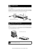
2 Install the Hub To install your hub on a flat surface, you do not need any special tools. Install the rubber footpads that are included in the package. Be sure the hub is positioned with at least 2 inches of space on all sides for ventilation. To install the hub in a rack, you need two Phillips screwdrivers: one size for the screws that attach the brackets to the hub and another size for the screws that attach the brackets to the mounting rack.
Connect the Hub to a Network Cascading refers to connecting hubs together to increase the number of ports or the number of users supported on the network. The 10BASE-T, BNC, or AUI ports can be used to cascade hubs together. Connect to a Network Using the 10BASE-T Ports The twisted pair cable extended from a 10BASE-T port (or UTP port) is called a twisted pair segment and can be up to 100 meters (m) in length.
You can cascade hubs together through any of the ports. The following illustration shows cascading hubs together in a hierarchical star through the 10BASE-T ports and indicates the setting of the Normal/Uplink push button on each hub.
Connect to a Network Using the BNC Port The BNC port on the rear panel of the hub is used for connecting to a thin coaxial segment. You can connect other Model EN516 or Model EN524 hubs, servers, workstations, or other devices to the BNC port. A BNC-T connector is inserted in the port, and the 50 Ω terminator terminates the connection at each end device. By using the BNC port for cascading, you treat each connected hub as just another node on the coaxial segment.
Connect to a Network Using the AUI Port The AUI port on the rear panel of the hub is normally used for connecting a thick coaxial segment. With the right type of transceiver, you can use the AUI port to connect to most types of network media, including 10BASE-T twisted pair cable or thin coaxial, thick coaxial, and 10BASE-FL fiber optic cables. Note: All transceivers connected to the AUI port must have the signal quality error (SQE) test function disabled.
Troubleshooting Information Refer to this table and the information that follows the table to troubleshoot your Model EN516 or Model EN524 hub. Symptom Cause Solution Amber Collision LED blinks. Data collision is normal on Ethernet networks. No action is required. Amber Collision LED blinks excessively. There is data collision on the network because the network is extremely busy or defective devices are connected on the network that cannot detect network traffic or collision.
Cable Connector Information Network Interface Cards Make sure the network interface cards installed in the workstations are in working condition and the software driver has been installed. Hub Integrity If required, verify the integrity of the hub by resetting it. Turn power to the switch off and then back on. If the problem continues and you have completed all the preceding diagnoses, contact NETGEAR Customer Support. For the phone number of the representative in your area, see “Customer Support.
RJ-45 Connector The RJ-45 connector (shown in the illustration with an RJ-45 plug) is used to connect workstations, hubs, and switches through unshielded twisted pair cable. The RJ-45 connector accepts four-pair Category 3 or Category 5 UTP cable. Only two pairs are used for 10BASE-T wiring.
BNC Connector The BNC connector for the hub supports 10 Mbps data transmission and connects the hub to other devices. BNC connector Center conductor 1 Ground shield 2 8149EA The BNC port on the hub, with the BNC T-connector and the 50 Ω terminator, is used for connecting to a thin coaxial segment.
Technical Specifications General Specifications Network Protocol and Standards Compatibility IEEE 802.3i, 10BASE-T, 10BASE-2, 10BASE-5 Ethernet Data Rate 10 Mbps, Manchester encoded Interface 16 10BASE-T ports (RJ-45) on the Model EN516 hub 24 10BASE-T ports (RJ-45) on the Model EN524 hub On both the Model EN516 and Model EN524 hubs: 1 BNC 10BASE-2 port 1 AUI port (15-pin D-type) Power 100–240 V, 50/60 Hz, (auto selection) 0.15 A maximum Physical Specifications Width: 13.
© 1998 by NETGEAR, Inc. All rights reserved. Trademarks Bay Networks is a registered trademark of Bay Networks, Inc. NETGEAR is a trademark of Bay Networks, Inc. All other trademarks and registered trademarks are the property of their respective owners. Statement of Conditions In the interest of improving internal design, operational function, and/or reliability, NETGEAR reserves the right to make changes to the products described in this document without notice.
NETGEAR, Inc. A Bay Networks Company 4401 Great America Parkway Santa Clara, CA 95054 USA Phone: 888-NETGEAR Customer Support Phone Australia: 1800-142-046 France: 0800-90-2078 Germany: 0130-817305 Japan: 0120-66-5402 Korea: 00308-11-0319 New Zealand: 0800-444-626 Sweden: 020-790086 United Kingdom: (44) 171-571-5120 U.S./Canada: 800-211-2069 Internet/World Wide Web The NETGEAR Web page is at http://NETGEAR.baynetworks.com.