NTI R 1275 Danner Dr Tel:330-562-7070 NETWORK TECHNOLOGIES Aurora, OH 44202 Fax:330-562-1999 www.nti1.com INCORPORATED XTENDEXTM Series ST-C5KVM-600-CE PS/2 KVM EXTENDER Installation and Operation Manual Manual 073-C Rev.
WARRANTY INFORMATION The warranty period on this product (parts and labor) is one (1) year from the date of purchase. Please contact Network Technologies Inc at (800) 742-8324 (800-RGB-TECH) or (330) 562-7070 or visit our website at http://www.nti1.com for information regarding repairs and/or returns. A return authorization number is required for all repairs/returns. COPYRIGHT Copyright © 2003 by Network Technologies Inc, all rights reserved.
Table of Contents Introduction.............................................................................................................................................................. 1 Materials .................................................................................................................................................................. 1 Features and Functions............................................................................................................................
Introduction Introduction The XTENDEX Series ST-C5KVM-600 PS/2 KVM Extender is designed to enable one PS/2 CPU to be controlled by two users, one local and one remote. The remote user can be located as much as 600 feet away from a PS/2 CPU via Category 5 shielded twisted-pair cable. The local user will be located near the PS/2 CPU. The XTENDEX Series ST-C5KVM-600 PS/2 KVM Extender is extremely simple to install and has been thoroughly tested to insure reliable performance.
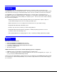
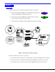
F E A T U R E S A N D F U N C T IO N S 1 2 4 1 2 5 - X T E N D E X N T I + R N e t w o r k T e c h n o lo g ie s In c N T I 6 3 N e t w o r k T e c h n o lo g ie s In c R X T E N D E X - 7 8 9 + (F r o n t V ie w ) (R e a r V ie w ) S T -C 5 K V M -6 0 0 L o c a l U n it Featuresand andFunctions Functions Features 1. Green LED- traffic indicator- illuminates when there is communication between the local and remote units. 2.
Limitations Limitations • Hot-plugging of devices is supported provided devices were originally connected at power-up. • Devices connected to the Local and Remote Units must be identical. Same mice, same keyboards, etc. • In order for two users to share a PS/2 CPU, the user in control must pause for at least 3 seconds before another user can take control. After the 3 second pause, either user can take control of the CPU.
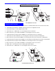
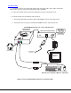
Installation Installation The Local Unit 1. Plug the cables of the Local Unit into the back of the CPU. (See Fig. 1.) a) Connect the purple 6 pin miniDIN cable end with the keyboard symbol on it to the keyboard port on the back of the CPU. b) Connect the green 6 pin miniDIN cable end with the mouse symbol on it to the mouse port on the back of the CPU. (Keyboard) (Mouse) c) Connect the blue 15HD cable end to the VGA port on the back of the CPU.
S T -C 5 K V M -6 0 0 L o c a l U n it F r o n t V ie w o f L o c a l U n it - N T I (F r o n t a n d R e a r V ie w ) R e a r V ie w + o f L o c a l U n it 1 5 H D F e m a le V id e o C o n n e c to r R N e t w o r k T e c h n o lo g ie s In c X T E N D E X Y e llo w G r e e n T r a ffic L E D P o w e r L E D 6 p in m in iD IN F e m a le C o n n e c to r C A T 5 C a b le to R e m o te U n it V G A M u lti- S c a n M o n ito r P S /2 K E Y B O A R D P S /2 M O U S E L o c a l U s e r 's K e y
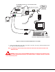
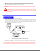
The Remote Unit 1. Position the Remote Unit such that the CAT5 cable, the monitor cable, device cables, and the AC adapter power connector can each reach the Remote Unit comfortably. 2. Connect the monitor cable to the female 15HD video connector on the Remote Unit. 3. Connect the device(s) to the Remote Unit (see Fig. 3). a. Connect the keyboard to the purple female 6 pin miniDIN connector on the Remote Unit. b. Connect the mouse to the green female 6 pin miniDIN connector on the Remote Unit.
4. Make sure the CAT5 cable has been installed in accordance with the “Preparation for Installation” instructions on page 3. Connect the CAT5 cable to the “Cat 5” port on the Remote Unit. (See Fig. 3.) When properly inserted the CAT5 cable end should snap into place. Note: If an RJ45 wall outlet is being used, connect the other end of the extension cable to the RJ45 wall outlet.
VideoQuality Quality Video Video quality adjustment is done automatically to assure the image is as clear as possible. Note: When the cable is longer than 300 feet some colored lines can be seen at the black-to-white transitions. This is a normal behavior and is caused by the different twisting rates of each pair of wires in the CAT5 cable.
Troubleshooting Each and every piece of every product produced by Network Technologies Inc is 100% tested to exacting specifications. We make every effort to insure trouble-free installation and operation of our products. If problems are experienced while installing this product, please look over the troubleshooting chart below to see if perhaps we can answer any questions that arise. If the answer is not found in the chart, please check the FAQs (Frequently Asked Questions) at our website at http://www.
1. NTI Model Number and Serial Number (from the bottom) of the Local Unit and the Remote Unit. Local M/N __________ S/N ______________ Remote M/N __________ S/N ______________ 2. The total length of the CAT5 extension cable in use.______ 3. Make and Model Numbers of the Monitor, Mouse, and Keyboard. Monitor ___________________________________ Mouse ___________________________________ Keyboard __________________________________ 4.