
User guide


159
Plug
Plug
T
T
RT
A
B
A
B
B
A
A
B
A
B
A
B
A
B
A
B
www.neutrik.com
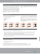
front rearfront rear front rear front rear
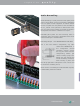
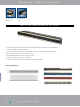
Front jack A for "listen in" Grey B jack for signal insertion Allows: 1 output to feed 2 inputs Upper (A) and lower (B) channel
separated
Solution for insert jack of mixing consoles
Split print by-passes the use of a specially
wired Y-cable.
A front
Mono - Send
Rear
Send - Return
(Stereo Jack)
B front
Mono - Return
(Red Jack)
With Switching Contacts
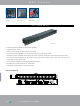
NYS-SPCR1
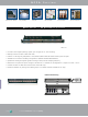
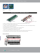
The NYS-SPP-L1 is a economical and remarkable sleek
designed 1/4“ modular patch panel for 19“ rack mount (19“
x 1U) with a reinforced metal housing. Each of it‘s 48 PCB
wired balanced channels (24 front pairs and correspond-
ing 24 rear pairs) can either be grounded separately or in
groups of inividually chooseable channel numbers (detailed
information see below).
The PCBs are held securely in place by being clamped
between the front and the rear panel, this grants an easy
reconfiguration of the patch panel without the danger of
loosing any small parts (e.g. nuts). The grey jack serves as an
easy and distinguishable normalling identification.
Standard configuration, when delivered, is Half Normalled
bottom row. The configuration can easily be changed by
just flipping the individual PCB. Inserting a plug into the
grey jack will always isolate the top against the bottom row.
Alternative solution for send / return applications by use of
NYS-SPCR1 module (see accessories below).
The following configurations are available:
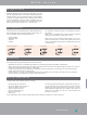
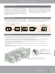
The flexible grounding system, applicable for each channel separately by simply attaching the loose supplied grounding clips
to the grounding pad of the corresponding channel, offers the following alternatives:
•
Individual (without grounding clip): Each channel ground (sleeve contact) is connected to the dedicated ground
contact of the incoming 1/4” plug only. This is the standard configuration for delivery.
•
Chassis common
: The relevant channel grounds (sleeve contacts; top and bottom row) is connected to the
ground flat tab via grounding clip and chassis.
•
Chassis top
: The dedicated top channel ground (sleeve contact) is connected to the ground flat tab via grounding
clip and chassis.
•
Chassis bottom
: The dedicated bottom channel ground (sleeve contact) is connected to the ground flat tab via
grounding clip and chassis.
grounding clip (slide onto the print)
Rear view detail:
Ground flat tab to be used with
FASTON
®
receptacle or to solder
the wire.
NYS Series NYS Series
Standard Turned Split Print
Configuration
Design Criteria
Grounding