
Datasheet


8
look for the logo
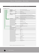
N C 3 FA H 1 - B - 0 - D
Definitions, Abbreviations & Useful Information see page 151.
N e u t r i k
®
P a r t N u m b e r G u i d e
P a r t N u m b e r G u i d e
Packaging: D Cable connector: Bulk packed
Assembly: D Chassis connector: Disassembled Push latch
Retention: w/o Latch Lock
-0 Retention Spring
Shell: B Black shell, gold contacts
BAG Black shell, silver contacts
Grounding: 0 Separate ground contact connected to shell, male only
1 Pin 1 & Panel & Shell connected, no separate ground contact
2 Separate ground contact connected to shell & panel, separate Pin 1
E Additional ground contacts
w/o number No ground / Shell contact (except 4 / 5 pole), female only
Termination: H Horizontal PCB mount
HL Laterial left PCB mount
HR Laterial right PCB mount
L Solder Cups
V Verticale PCB mount
Y IDC for wires (no ground)
M3 Mounting holes with M3 thread
M25 Mounting holes with M2.5 thread
- Not applicable
Series: A, AA, B, BA, D, DL, DLX, MPR, P, PX, RX, X, XX
Gender: F Female
M Male
Number of Contacts: 3, 4, 5, 6, 7, 8, 12
Connector Type: A Adapter
AC powerCON
B BNC
C XLR
D dummyPLUG
E RJ45
F RCA / CINCH
J (MJ, RJ, SJ) Jack
K Cable Assemblies
L Loudspeaker
M Modules
O Fiber Connector
P Plugs
PP Patch Panel
R Circular Connector
T Transformer