BUCKSTOVE MODEL 74 ROOM HEATER NON-CATALYST FIREPLACE INSERT & FREESTANDING FEATURES PREPARATIONS INSTALLATION SAFETY OPERATION MAINTENANCE SAFETY NOTICE IF THIS HEATER IS NOT PROPERLY INSTALLED, A HOUSE FIRE MAY RESULT. FOR YOUR SAFETY, FOLLOW THE INSTALLATION INSTRUCTIONS. CONTACT LOCAL BUILDING OR FIRE OFFICIALS CONCERNING RESTRICTIONS AND INSTALLATION INSPECTIONS IN YOUR AREA.
TABLE OF CONTENTS Important Instructions......................................................................................................... 2 SECTION I: Introduction ................................................................................................... 3 Type of wood and loading procedures …………………………………….. ……………..3 SECTION II: Masonry Insert Installation........................................................................... 4 Installation Preparation-Fireplace.........................
INSTALLATION, OPERATION, AND MAINTENANCE INSTRUCTIONS MODEL 74 BEFORE INSTALLING YOUR NEW BUCK STOVE, READ THE ENTIRE INSTRUCTION MANUAL IMPORTANT INSTRUCTIONS WARNING THESE UNITS GENERATE A LOT OF HEAT, SO TREAT THEM WITH CARE. HOT WHILE IN OPERATION! KEEP CHILDREN, CLOTHING AND FURNITURE AWAY. CONTACT MAY CAUSE SKIN BURNS.”DO NOT USE CHEMICALS OR FLUIDS TO START THE FIRE.” “DO NOT BURN GARBAGE OR FLAMMABLE FLUIDS.” DO NOT CONNECT TO ANY DISTRIBUTION DUCT OR SYSTEM.
CAUTION YOUR CHIMNEY MUST BE CORRECTLY SIZED. A CHIMNEY THAT IS TOO SMALL OR LARGE IN DIAMETER, OR TOO SHORT, CAN CAUSE YOUR STOVE TO SPILL SMOKE WHEN THE DOOR IS OPENED. SECTION I INTRODUCTION Your new MODEL 74 is a non-catalytic unit designed to meet the most stringent emissions standards without the use of a catalytic combustor. This effect is achieved through the use of secondary air which is mixed with primary air in the unit’s firebox.
SECTION II MASONRY INSERT INSTALLATION The Model 74 may be installed using an all masonry fireplace built in accordance with the Uniform Building Code and National Fire Protection Association (NFPA). The first step in this type of installation is to determine the acceptability of the fireplace and chimney for use with a woodstove. Both the construction and condition of the fireplace are important considerations when installing a woodstove.
POSSIBLE TOOLS NEEDED FOR INSTALLATION If you decide to install your own stove, there are several hand tools you may need to do the job. If you do not already have them, they are readily available at most hardware stores.
SAFETY NOTICE If this appliance is not properly installed, a house fire may result. For your safety, follow the installation directions. Contact local building or fire officials about restrictions and installation inspection requirements in your area.
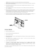
INSTALLATION PROCEDURE (Use a chimney connector or a Listed Direct or Positive Connect) (See Page 6.) POSITIONING THE HEATER When positioning the heater, the following conditions MUST be met! (See Figure 2.) 1. 2. The front of the damper opening must be positioned BEHIND the rear edge of the lintel to ensure proper draft. (See Figure 2.) Center the heater in the fireplace opening.
9. NOTE: Mount the top trim panel so that it sits in front of the top of the side trim panels.. Obtain the brass trim kit provided with insert kit and slip over the top and sides of trim panels. (Top ends of brass may need to be trimmed to fit.) 10. Using insulation provided, peel and stick to back of panels overlapping fireplace dimensions by 1" on each side and top. (See Figure 4.) 11. Next using high heat silicone or furnace cement run heavy bead of caulking around where panels meet the stove.
CAUTION THE UNIT IS PAINTED WITH A SPECIALLY FORMULATED HIGH TEMPERATURE PAINT THAT CURES DURING THE FIRST TWO OR THREE FIRINGS. YOU MAY NOTICE A SLIGHT SMOKING EFFECT AND AN ODOR OF BURNING PAINT WHEN YOU BUILD THE FIRST FIRES. THIS IS NORMAL AND IS NOT A CAUSE FOR ALARM. IN SOME CASES, THESE FUMES WILL ACTIVATE A SMOKE ALARM. OPENING A WINDOW NEAR THE UNIT WILL ALLOW THESE FUMES TO ESCAPE. DO NOT BUILD A LARGE, ROARING FIRE UNTIL THIS CURING IS COMPLETE OR THE HEATER FINISH MAY BE DAMAGED.
SECTION III PRE-FAB INSERT INSTALLATION The Model 74 has been tested with the following UL listed manufactured Pre-Fab Fireplaces: Heatilator Tempco Marco Woodside Security Preway FMI Majestic The Model 74 will fit any of the models that are large enough to accept them. NOTE: A full chimney liner is required in a Zero Clearance or pre-fab fireplace. NOTE: The ash lip, smoke baffle, and smoke shelf may be removed if necessary to provide room for these models.
SECTION IV RESIDENTIAL FREESTANDING INSTALLATION Select an installation location that will give the best airflow from the front of the heater to the remainder of the home. PREPARING THE STOVE FOR INSTALLATION 1. Inspect the unit for any obvious physical damage. 2. Plug the power cord into a 115V AC outlet to test the motor and fan when optional motor is being used. “Do not run power cord under unit or in high traffic areas”. 3. Check the primary air draft control to ensure that it slides freely. 4.
Chimney This model is designed for connection to the following listed 2100º UL103 HT chimneys and parts. Follow chimneys manufacturer's instructions carefully. Simpson Duravent Security Selkirk Metal Bestos Metal Fab Airjet Jakes Evans This room heater must be converted to (1) a chimney complying with the requirements for Type HT chimneys in the Standard for chimneys, Factory-Built, Residential, Type and Building Heating Appliance, UL 103, or (2) a code approved masonry chimney with a flue liner.
Step (b): Calculate R of proposed system. 4” brick of C=1.25, therefore Rbrick = 1/C = 1/1.25 =0.80 1/8” mineral board of K = 0.29, therefore Rmin.bd. =1/029 x0.125 = 0.431 Step (c): Compare proposed system R of 1.231 to specified R of 0.893. Since proposed system R is greater than required , the system is acceptable.
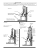
ROOF CEILING COLLAR 3 SHEET METAL SCREWS OR RIVETS 3 SHEET METAL SCREWS Figure 5 ATTIC CEILING 18" MIN. TEE BOX ASSEM. CENTER LINE OF ELBOW CLEAN OUT ACCESS "TEE" BOX ASSEM. WALL PASS-THROUGH CONNECTOR WALL MARK PLUMB LINE FLOOR PROTECTOR Figure 6 B. Wall Exit Into Metal Tee-Box 1. Mark the plumb line on the wall directly behind the center of the heater. (See Figure 6.) NOTE: When using 24# ga. minimum blue or black steel pipe, maintain 18" between pipe and ceiling.
3. Measure up so there will be at least 1/4" rise per foot of horizontal connector pipe, maintaining clearances to the ceiling as noted in (Figure 6 Page 14.) This will give you the center of the hole for the chimney penetration. 4. After locating the center of the penetration, install the tee-box and chimney as per the chimney manufacturer's specifications. 5. Connect the chimney connector to the tee-box using #24 ga. minimum blue or black steel connector pipe. DO NOT use galvanized pipe.
Connectors may pass through walls or partitions constructed of combustible material if the connector is: (a) Either listed for wall pass-through or is routed through a device listed for wall passthrough and is installed in accordance with the conditions of the listing. (b) Selected or fabricated in accordance with the conditions and clearances as stated in the NFPA-211 Code.
ROOF CEILING ROOF CEILING CHIMNEY CONNECTOR COLLAR Figure 8 This unit may be installed using the following double wall close clearance chimney systems: (1) 6" Simpson Dura-Vent double wall chimney connector “Type DVL” and 6" Simpson Dura-Vent 2100º HT. “Type DP” chimney. (2) 6" Security Type DL double wall connector and 6" Security Type "ASHT" High Temp Chimney. (3)6" Selkirk Metal Bestos Model “DS” double wall connector- 6" Selkirk Metal Bestos Model SSII Type HT Chimney System.
FINAL CHECK 1. Recheck the specified clearances. 2. Remove all foreign material from the firebox area. 3. Open the primary air draft. 4. Plug the power cord into a 115V AC outlet when using with optional motor. ”Do not run power cord under unit or in high traffic areas”. 5. Place crumpled pieces of newspaper in the stove. Light it and close the door. Ensure that the stove draws properly through the primary draft. 6. Check for smoke leaks around the door.
CLEARANCES FOR MODEL 74 MINIMUM CLEARANCES TO COMBUSTIBLES RESIDENTIAL SINGLE WALL CONNECTOR WITHOUT CLOSE CLEARANCE SHIELDS BACK WALL F H C F B G B CD CD SIDE WALL C EE DG AA Figure 9 MODEL A B MODEL 74 25" 8" C 10.5" D E F G H 8" 8" 6" 20" 10” NOTE: All clearances are to combustibles without low clearance shields and using single wall pipe and minimum floor protector. The clearances above may be reduced. Follow NFPA-211 codes if available or follow instructions on next page.
CLEARANCES FOR MODEL 74 MINIMUM CLEARANCES TO COMBUSTIBLES RESIDENTIAL / MOBILE HOME DOUBLE WALL OR SHIELDED SINGLE WALL CONNECTOR WITH CLOSE CLEARANCE SHIELDS BACK WALL B F H C F B G C D SIDE WALL C EE C D DG AA Figure 10 MODEL A B C D E F G H MODEL 74 23" 4" 6.5" 4" 8" 6" 20" 10” NOTE: All clearances are to combustibles with all low clearance shields and double wall pipe and minimum floor protector.
CLEARANCES FOR MODEL 74 MINIMUM CLEARANCES TO COMBUSTIBLES RESIDENTIAL / MOBILE HOME DOUBLE WALL OR SHIELDED SINGLE WALL CONNECTOR WITHOUT CLOSE CLEARANCE SHIELDS BACK WALL B F H C F B G SIDE WALL C C D EE CD DG AA Figure 10 MODEL A B C D E F G H MODEL 74 25" 4" 6.5" 4" 8" 6" 20" 10” NOTE: All clearances are to combustibles with all low clearance shields and double wall pipe and minimum floor protector.
Installation of Close Clearance Shields (Optional) 1. Taking close clearance side shields, hold up to side of stove leaving 1/4" gap between shield and top of stove. 2. Make reference mark in center of pre-punched hole in top & bottom of shield. Drill two (2) 3/32" holes in back of unit on each side. Insert self-tapping screws in through shield into stove. 3. Drill two (2) 3/16" holes in the sides of the stove where the shield meets the front side. Insert two (2) 3/8" self-tapping screws. 4.
CLEARANCES FOR MODEL 74 ALCOVE INSTALLATION DOUBLE OR SHIELDED SINGLE WALL CONNECTOR WITH CLOSE CLEARANCE SHIELDS BACK WALL C BHG B FJ SIDE WALL C E IE D DK AA Figure 11 MODEL A B C D E H I J K MODEL T-74 23" 4" 6.5" 84" 36" 10” 8” 6” 20” NOTE: Clearances to be used with double wall low clearance pipe and low clearance shield kit only.
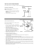
SECTION V FREESTANDING MOBILE HOME INSTALLATION FLOOR PROTECTION Floor protector must be 3/8" minimum thickness non-combustible material or equivalent. How to use alternate materials and how to calculate equivalent thickness. An easy means of determining if a proposed alternate floor protector meets requirements listed in the appliance manual is to follow this procedure: 1. Convert specification to R-value: R-value is given—no conversion is needed.
CHIMNEY This model is designed for connection to the following, 2100° UL 103 HT chimneys and parts, Simpson Duravent, Security, Selkirk Metal Bestos and Metal Fab. Air Jet, Jakes Evans pipe. Follow chimney manufactures instructions carefully. TOOLS FOR INSTALLATION Drop cloth 3/32" Metal drill bit 5/16" Magnetic socket chuck adapter, 5/16" wrench (box or socket) or adjustable wrench Jigsaw with masonry, metal and wood blades PREPARING THE HEATER FOR INSTALLATION 1.
PREPARING THE LOCATION FOR ROOM HEATER 1. Select an installation location that will give the best airflow from the front of the heater to the remainder of the home. CAUTION THE STRUCTURAL INTEGRITY OF THE MOBILE HOME FLOOR MUST BE MAINTAINED. (MOVE OPENING AND/OR REPOSITION HEATER LOCATION IF NECESSARY). 2. Place the protective floor pad in position. For minim floor protection (See Pages 12,20,21,23.) 3. Place the unit on the pad making sure the minimumum clearance specifications are met. 4.
14. From under the mobile home, slip the duct up through the 4-1/4" hole. Push up until the face of the outside air duct contacts the underside of the floor of the mobile home. For certain floor thickness, you may have to shorten the length of the outside air duct. 15. Secure the outside air duct to the floor using the four (4) #10x1 screws provided. (See Figure 12A.) RAIN CAP RAIN CAP 24" min. (610 mm) 24" min. (610 mm) 36" TYP. FLASHING 36" TYP. FLASHING RADIATION SHIELD RADIATION SHIELD 20 FT.
2. After locating the center of the hole install the ceiling support box, chimney flashing and rain cap. Only use2100° UL 103 HT chimney and parts listed in this manual per the chimney manufactures instruction . CAUTION REFER TO CHIMNEY MANUFACTURER’S INSTRUCTIONS FOR ASSEMBLY AND DISASSEMBLY OF CHIMNEY PARTS. BE SURE TO FOLLOW CHIMNEY INSTRUCTIONS FOR PROPER CLEARANCES TO COMBUSTIBLE AND PROPER AIR SPACING REQUIRED. 3.
FINAL CHECK 1. Recheck the specified clearances. 2. Remove all foreign material from the firebox area. 3. Open the primary air draft. 4. Plug the power cord into a 115V AC outlet when using with optional motor. Do no run power cord under unit or in high traffic areas. 5. Place crumpled pieces of newspaper in the stove. Light it and close the door. Ensure that the stove draws properly through the primary draft. 6. Check for smoke leaks around the door. 7.
SECTION VI WOOD HEATER SAFETY Certain safety hazards are inherent in any wood heater installation. You should be aware of these so that a safe and proper installation can be made. 1. FAULTY CHIMNEY: An older masonry chimney should be thoroughly checked to be sure there are no holes or weak spots which could allow sparks or hot gases to escape. 2. HEAT CONDUCTION: Placing combustible materials too close to a heater or chimney can be a fire hazard.
SECTION VII OPERATION This section of the manual is to help you get the maximum efficiency and maximum smoke (particulate) reduction from your heater. If you should experience any difficulty or have any questions concerning your heater, contact your dealer for assistance. NOTE: The manufacturer recommends that for maximum performance burn seasoned natural hard wood. Build a fire for maximum efficiency. This model burns wood and extracts heat so efficiently, a large fire is not necessary.
SECTION VIII TROUBLESHOOTING PROBLEM 1. Sluggish Heater POSSIBLE CAUSE 1. Obstruction in Chimney 2. Improperly sealed trim kit or direct connect kit 3. Manual damper in chimney is closed 4. Wet or unseasoned wood being burned 5. Poor chimney draft 6. Improper wood loading 32 SOLUTION 1. Check for and remove obstruction 2. (a) Check trim kit gasketing seal to fireplace and gasket as necessary to seal unit. Gasket under front bottom of stove if needed. (b) Check seal if using direct connect and correct.
PROBLEM 2. High fuel consumption 3. Backpuffing POSSIBLE CAUSE SOLUTION 1. Improper regulation of draft or inlet air 1. (a) Close inlet air control as much as possible to maintain desired heat output. (b) Check gaskets, reinstall fiberglass gasketing around doors and glass as necessary 2. Improper door fitting 2. Check door gasket, check adjustment of door latch 1. Gusts of Wind 1. (a) Smoke shelf in chimney is filled with creosote & ash (b) Chimney may need wind diverter.
NEW BUCK CORPORATION (NBC) "LIMITED WARRANTY" FOR THE BUCK STOVE PLEASE READ THIS WARRANTY CAREFULLY PRODUCTS COVERED This warranty covers the New Buck Stove heating unit, as long as it is owned by the original purchaser, including optional and standard accessories purchased at the same time, subject to terms, limitations, and conditions herein set out. PRODUCTS NOT COVERED This warranty does not cover the following: Glass; Refractory material such as refractory cement or firebrick; Gaskets.
If for any reason you are dissatisfied with the suggested procedures, you may contact us in writing at: New Buck Corporation Customer Service Department P. O. Box 69 Spruce Pine, NC 28777 CONDITIONS AND EXCLUSIONS A. Replacement of parts may be in the form of new or fully reconditioned parts, at NBC's option. B There is no other express warranty. All implied warranties of Merchantability and Fitness for Use are limited to the duration of the Express Warranty. C.