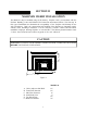
NON-CATALYTIC UNIT MODEL 81 BUCK STOVE SAFETY NOTICE FEATURES PREPARATIONS OPERATION INSTALLATION MAINTENANCE SAFETY IF THIS HEATER IS NOT PROPERLY INSTALLED, A HOUSE FIRE MAY RESULT. FOR YOUR SAFETY, FOLLOW THE INSTALLATION INSTRUCTIONS. CONTACT LOCAL BUILDING OR FIRE OFFICIALS CONCERNING RESTRICTIONS AND INSTALLATION INSPECTIONS IN YOUR AREA. MANUFACTURED BY NEW BUCK CORPORATION - SPRUCE PINE, NC 28777 This product is listed by Warnock-Hersey International, Inc. to the UL Standard No.
TABLE OF CONTENTS Important Instructions......................................................................................................... 3 SECTION I: Introduction ................................................................................................... 4 SECTION II: Masonry Insert Installation........................................................................... 5 Installation Preparation-Fireplace.......................................................................................
2
INSTALLATION, OPERATION, AND MAINTENANCE INSTRUCTIONS MODEL 81 READ THIS FIRST IMPORTANT INSTRUCTIONS WARNING THESE UNITS GENERATE A LOT OF HEAT, SO TREAT THEM WITH CARE. HOT WHILE IN OPERATION. KEEP CHILDREN, CLOTHING AND FURNITURE AWAY. CONTACT MAY CAUSE SKIN BURNS. READ ALL INSTRUCTIONS BEFORE INSTALLING AND USING THE APPLIANCE. FAILURE TO FOLLOW INSTRUCTIONS MAY RESULT IN PROPERTY DAMAGE, BODILY INJURY, OR EVEN DEATH. SAVE THESE INSTRUCTIONS FOR FUTURE REFERENCES.
CAUTION YOUR CHIMNEY MUST BE CORRECTLY SIZED. A CHIMNEY THAT IS TOO SMALL OR LARGE IN DIAMETER, OR TOO SHORT, CAN CAUSE YOUR STOVE TO SPILL SMOKE WHEN THE DOOR IS OPENED. SECTION I INTRODUCTION Your stringent achieved the unit's Buck Stove is a non-catalytic unit designed to meet the most emissions standards without the use of a catalytic combustor. This effect is through the use of a secondary air which is mixed with primary air in firebox. For peak performance we suggest the use of hard seasoned wood.
SECTION II MASONRY INSERT INSTALLATION The Model 81 may be installed using an all masonry fireplace built in accordance with the Uniform Building Code and National Fire Protection Association (NFPA). The first step in this type of installation is to determine the acceptability of the fireplace and chimney for use with a woodstove. Both the construction and condition of the fireplace are important considerations when installing a woodstove.
MINIMUM CLEARANCES 1. The hearth must be of masonry construction and must extend a minimum of 16” in front of the firebox opening and a minimum of 8" to either side of the firebox opening. 2. If there is not minimum hearth protection from the front of the firebox opening and the front of the masonry hearth, a floor protector must be used in front of the hearth to protect combustible materials. The floor protector must be 3/8" minimum thickness noncombustible material or equivalent.
POSSIBLE TOOLS NEEDED FOR INSTALLATION If you decide to install your own stove, there are several hand tools you may need to do the job. If you do not already have them, they are readily available at most hardware stores. Caulking gun Large adjustable wrench (may not be needed) Drop Cloths Vacuum cleaner or whisk broom Flashlight 1 tube of RTV silicone, Code 103 or 106, or high temperature rubber cement rated between 450o F. - 600o F.
Installation Procedure Positioning the Heater NOTE: It is not necessary to direct connect this unit unless installed in improper drawing fireplace or oversized flue. It is recommended a chimney connector be installed from the appliance flue collar to the first fireplace chimney section. WARNING WHEN POSITIONING THE HEATER, THE FOLLOWING CONDITIONS MUST BE MET! 1. The front of the damper opening must be positioned BEHIND the rear edge of the lintel to ensure proper draft. 2.
Figure 2 7. Slide the unit back into the fireplace. Check to be sure that the trim panels are properly positioned and lie flat against the front of the fireplace. If one of more of the panels is out of position, slide the unit out and reset by loosening the mounting screws and repositioning in the slot. 8. Reinstall the top trim panel by sliding the rear lip of the top trim panel underneath the front lip of the mounting bracket already secured to top of unit.
14. Slide the unit back into the fireplace. Check to be sure that the trim panels (and brass) are properly positioned and lie flat against the front of the fireplace. If panels are out of position, slide the unit out and reset by loosening the mounting screws and repositioning in the slot. With bar, lift stove in front. Place insulation across front and the surface of hearth or bottom of fireplace, to make complete seal. 15.
4. Place crumpled pieces of newspaper in the stove. Light it and close the doors. Ensure that the stove draws properly through the primary draft. NOTE: “Do not use grate or elevate fire. Build wood fire directly on floor of stove.” 5. Check for smoke leaks around the doors. 6. Open the doors and check for smoke escaping from the front of the stove. Smoking usually indicates a defective or poorly positioned chimney.
SECTION III PRE-FAB INSERT INSTALLATION The Model 81 may be installed into any UL listed pre-fabricated fireplace that is large enough to accept it. NOTE: When installing the Model 81 into a Pre-Fab Zero-Clearance fireplace, a UL-1777 LINER must be installed the Full Length of the chimney and attached to the flue exit of the Insert. NOTE: The ash lip, smoke baffle, and smoke shelf of the pre-fab fireplace may be removed if necessary to provide room for these models.
SECTION IV RESIDENTIAL FREESTANDING INSTALLATION MINIMUM CLEARANCE TO COMBUSTIBLE MATERIAL PREPARING THE STOVE FOR INSTALLATION 1. Inspect the unit for any obvious physical damage. NOTE: Plug the power cord into a 115V AC outlet to test the fan and motor. Set switch to “Manual” and rheostat to “High” position to ensure motor operates properly. Route the cord to prevent damage to the cord insulation from heat and sharp objects.
ALTERNATE FLOOR PROTECTORS MATERIAL Floor protector must be 3/8" minimum thickness non-combustible material or equivalent. With the floor protector or hearth extension material specified as one layer of 2" thick brick with a K* factor of 5.0, you may use alternate materials as long as the K* factor (s) is calculated as follows: FORMULA: Required thickness = (K of alternate material/K of millboard) X (thickness of millboard) EXAMPLE: An alternate inorganic non-combustible millboard with a K* of .
Chimney These models are designed for connection to: (1) Simpson Duravent - Dura Black (2) Metal Fab (3) Ameritec - BSR NOTE: This Room Heater must be converted to (1) a chimney complying with the requirements for Type HT chimneys in the Standard for chimneys, Factory-Built, Residential, Type and Building Heating Appliance, UL 103, or (2) a code approved masonry chimney with a flue liner. The chimney size should not be less than nor more than 3 times greater than the cross-sectional area of the flue collar.
three (3) sheet metal screws or rivets. Next, install an optional New Buck Corporation chimney connector to the flue exit of the heater or you may use “Ell” brackets to fasten the pipe to the stove. 4. Install Single Wall Connector and chimney system per manufacturer’s written operating instructions. See manufacturer’s list of tested pipes in this manual. Figure 5 Figure 6 B. Wall Exit Into Metal Tee-Box 1. Mark the plumb line on the wall directly behind the center of the heater. (See Figure 6.
maintaining clearances to the ceiling as noted in Figure 6. This will give you the center of the hole for the chimney penetration. 4. After locating the center of the penetration, install the tee box and chimney as per the chimney manufacturer's specifications. 5. Connect the chimney collar to the tee-box using #24 ga. minimum blued or black steel connector pipe. (DO NOT USE GALVANIZED PIPE.
NOTE: In addition, a connector to a masonry chimney shall extend through the wall to the inner face or liner but not beyond, and shall be firmly cemented to masonry. EXCEPTION: A thimble may be used to facilitate removal of the chimney connector for cleaning, in which case the thimble shall be permanently cemented in place with hightemperature cement. 2. Once the through-the-wall thimble codes are met, simply connect the chimney collar to the wall pass-through connector using #24 ga.
CEILING SUPPORT BOX OPTIONAL SINGLE WALL PIPE CHIMNEY CONNECTOR Figure 8 Close Clearance Installation using: (1) 6" Simpson Dura-Vent single wall chimney connector Dura Black and 6" Simpson Dura-Vent 2100 Deg Ht. “Type DP” chimney. (2) 6" Metal Fab Type single wall connector- 6" Metal Fab 2100 HT chimney. (3) Ameritec. For minimum clearances see pages 20 & 21. ALCOVE INSTALLATION CLEARANCES Must use 6" Single Wall Connector and 6" Type HT Pipe listed for close clearance reduction listed in this manual.
FINAL CHECK 1. Recheck the specified clearances. 2. Remove all foreign material from the firebox area. 3. Open the primary air draft. NOTE: Plug the power cord into a 115V AC outlet. Set switch to “Manual” and rheostat to “High” position to ensure motor operates properly. Route the cord to prevent damage to the cord insulation from heat and sharp objects. Keep the cord out of the way of traffic to prevent damage caused by tripping, etc. 4. Place crumpled pieces of newspaper in the stove.
CLEARANCES FOR MODEL 81 MINIMUM CLEARANCES TO COMBUSTIBLES FREESTANDING BACK WALL SIDE WALL B G C A 8" F C D D C 8" E HEARTH PAD A B 16" D Figure 9 MODEL A B C D MODEL 81 23" 23" 25" 16" NOTE: All clearances are to combustibles without low clearance shields and using single wall pipe and minimum floor protector. Clearances above may be reduced. Follow NFPA-211 codes if available or follow instructions on next page. * Floor Protector at rear needed for thru-the-wall exit only.
CLEARANCES FOR MODEL 81 MINIMUM CLEARANCES TO COMBUSTIBLES SINGLE WALL CHIMNEY CONNECTOR AND OPTIONAL SHIELDS, MOBILE HOME AND ALCOVE INSTALLATIONS BACK WALL SIDE WALL AB CE 8" D C DC B 8" 16" AC Figure 10 MODEL A B C D MODEL 81 12" 16" 12.5" 12" NOTE: All clearances are to combustibles using single wall pipe and all low clearance shields and minimum floor protector. *Floor protector at rear needed for thru-the-wall exit only.
INSTALLATION OF CLOSE CLEARANCE SHIELDS (Optional) 1. Take rear close clearance shield and center with back of stove using self-tapping screws. 2. Remove self-tapping screws from rear of stove. Align holes in side shield with holes in rear shield and attach to stove. 3. Before tightening the screws, insert the front end of the shield behind the side angle on the front side of the stove. Use the same step to install side shield on the opposite side of the stove. 4.
SECTION V FREESTANDING MOBILE HOME INSTALLATION FOR MINIMUM CLEARANCES SEE PAGE 21. FLOOR PROTECTION Floor protector must be 3/8" minimum thickness non-combustible material or equivalent. With the floor protector or hearth extension material specified as one layer of 2" thick brick with a K* factor of 5.
TOOLS FOR INSTALLATION Drop cloth 3/32" Metal drill bit 5/16" Magnetic socket chuck adapter, 5/16" wrench (box or socket) or adjustable wrench Jigsaw with masonry, metal and wood blades. WARNING: DO NOT INSTALL IN A SLEEPING ROOM. PREPARING THE HEATER FOR INSTALLATION 1. Inspect the unit for any obvious physical damage. NOTE: Plug the power cord into a 115V AC outlet. Set switch to “Manual” and rheostat to “High” position to ensure motor operates properly.
5. Next, remove the four (4) screws holding the heater to the stand. Position heater out of the way of the installation area. 6. Check that the pedestal stand is still aligned with the marks and now, mark the outside air opening of the stand on the pad. 7. Next, mark the center line of the outside air opening. Set stand aside for now. 8. Next, cut a 4 1/4" diameter hole in the pad and continue through the floor. CAUTION THE STRUCTURAL INTEGRITY OF THE MOBILE HOME FLOOR MUST BE MAINTAINED.
RAIN CAP RAIN CAP 24" min. (610 mm) 24" min. (610 mm) 36" TYP. FLASHING 36" TYP. FLASHING RADIATION SHIELD RADIATION SHIELD 20 FT. MAX. OUTSIDE AIR DUCT THROUGH FLOOR WHEN MOBLE HOME IS NOT UNDERPENNED OUTSIDE AIR DUCT THROUGH UNDERPENNED Ceiling Exit (Using Close Clearance Listed Chimney) 1. Suspend a plumb bob from the ceiling above the unit so that the weight is hanging in the center of the flue exit. ( A small weight on a string will serve as a plumb bob.
(a) Chimney pipe is 3' higher than roof at the point where it penetrates the roof. (b) Chimney pipe height is at least 2' higher than any part of the roof within 10' of the chimney. (See Figure 12.) 4. Next, install a New Buck Corporation chimney connector to the flue of the heater or use 3 “Ell” brackets and secure to the top of the heater and pipe. 5. Using single wall chimney connector, connect the heater to the chimney by following manufacturer’s installation instructions exactly. (See Figure 13.
4. Place crumpled pieces of newspaper in the stove. Light it and close the doors. Ensure that the stove draws properly through the primary draft. 5. Check for smoke leaks around the doors. 6. Open the doors and check for smoke escaping from the front of the stove. Smoking usually indicates a defective or poorly positioned chimney. Some chimneys with a marginal draft can be preheated by lighting newspaper and holding it near the open damper with a poker or fire tong.
The chimney and chimney connector should be inspected once every two months. Any buildup of soot should be removed to prevent the risk of a chimney fire. To remove chimney or chimney connector: Remove screws or fasteners. Remove pipe and clean with steel brush. Replace chimney or chimney connector, and replace screws and/or fasteners. CAUTION NEVER USE GASOLINE, GASOLINE TYPE LANTERN FUEL, KEROSENE, CHARCOAL LIGHTER FLUID OR SIMILAR LIQUIDS TO START OR "FRESHEN UP" A FIRE IN THE HEATER.
BUILDING A FIRE 1. Open the door. 2. Open the primary air control located on right side of stove under hearth. To close push all the way in. To open pull all the way out. Adjustments to airflow may be made by positioning the handle anywhere in between. 3. Twist two pieces of non-colored newspaper into a roll and place them on the floor of the firebox. 4. These models are not designed for the use of grates, andirons or other methods of supporting the fuel. 5.
ROOM AIR BLOWER OPERATION Your heater is equipped with a room air blower. For operation and wiring see Figure 14. For your convenience your heater is equipped with a rheostat with which you are able to select the air flow. The auto and manual switch will allow you to select the position at which the thermostat will function.
SECTION VIII TROUBLESHOOTING PROBLEM 1. Sluggish heater POSSIBLE CAUSE 1. Obstruction in chimney 2. Improperly sealed trim kit or direct connect kit 3. Wet or unseasoned wood being burned. 4. Poor chimney draft 2. High Fuel Consumption 1. Improper regulation of draft or inlet air 2. Improper door fitting 3. Backpuffing 1. Gusts of Wind SOLUTION 1. Check for and remove obstruction 2. (a) Check trim kit gasketing seal to fireplace and gasket as necessary to seal unit.
EPA COMPLIANCE STATUS The Model 81 heater meets the U.S. Environmental Protection Agency’s Emission limits for wood heaters sold after July 1, 1992. Under specific conditions this heater has been shown to deliver heat at rates ranging from approximately 10,000 to 45,000 BTU/hr for the Model 81. MODEL 81 WOOD STOVE (41) (5) (39) (4) (20) (32) (16) (1) 1 (11) (7) (13) (37) & (38) (14) (40) (21) (18) (33) (15) (31) (27) (3) (8) (12) (2) (19) (35) 6 (36) (10) 1. 2. 3. 4. 5. 6. 7. 8. 9. 10. 11.
REPLACEMENT PARTS FOR THE MODEL 81 1. Air Control Bar 2. Door Handle Assembly 3. Door Latch 4. Door Handle Washer 5. Front door bushing 6. Door Gold 7. Door Black 8. Carlingl Fan Auto/Man Switch 9. Thermostat 110 disc 10. Power Cord 11. Strain Relief 12. Motor 13. Rheostat 14. Rheostat knob 15. Glass 16. Glass, Bay side 17. Glass clip 18. Spring Handle 19. “U” Drive Screw 5/16" x 1/2" 20. Top Firebox Blanket 21. Secondary Air Tube 22. Bottom Firebox Blanket 23. Primary Air Block 24. Side Brass Overlay 25.
NEW BUCK CORPORATION (NBC) “LIMITED WARRANTY” FOR THE BUCK STOVE PLEASE READ THIS WARRANTY CAREFULLY PRODUCTS COVERED This warranty covers the new Buck Stove heating unit, so long as it is owned by the original purchaser, including optional and standard accessories purchased at the same time, subject to terms, limitations, and conditions herein set out. PRODUCTS NOT COVERED This warranty does not cover the following: Glass; Refractory material such as refractory cement or firebrick; Gaskets.
New Buck Corporation Customer Service Department P. O. Box 69 Spruce Pine, NC 28777 CONDITIONS AND EXCLUSIONS A) Replacement of parts may be in the form of new or fully reconditioned parts, at NBC's option. B) There is no other express warranty. All implied warranties of Merchantability and Fitness for Use are limited to the duration of the Express Warranty.