OPERATIONS MANUAL FOR THE MODEL DV23ZC DIRECT VENT ZERO CLEARANCE GAS FIREPLACE APPROVED FOR MOBILE HOME INSTALLATION WARNING: If the following information in this manual is not followed exactly, a fire or explosion may result causing property damage, personal injury, or loss of life. -DO NOT STORE OR USE GASOLINE OR OTHER FLAMMABLE VAPORS AND LIQUIDS IN THE VICINITY OF THIS OR ANY OTHER APPLIANCE. -WHAT TO DO IF YOU SMELL GAS * Do not try to light any appliance.
TABLE OF CONTENTS Introduction.......................................................................................................................... 3 Specifications ....................................................................................................................... 3 Installation ........................................................................................................................... 5 Location and Clearance ..........................................................
2
INTRODUCTION This instruction manual will help you obtain a safe, efficient, dependable installation for your appliance and vent system. Please read and understand these instructions before beginning your installation. The model DV23ZC is a sealed combustion, air circulating gas appliance designed for residential and mobile home applications. The appliance must be installed with Dura-Vent GS vent system that is routed to outside atmosphere. It is also listed for bedroom installations.
NOTE: Installation and repair should be performed by a qualified service person. The appliance should be inspected annually by a qualified professional service person. More frequent inspections and cleanings may be required due to excessive lint from carpeting, bedding material, pet hair, etc. It is imperative that the control compartment, burners and circulating air passage ways of the appliance be kept clean.
GENERAL INFORMATION LOCATION AND CLEARANCE Make sure your installation location provides adequate combustion and ventilation air. In selecting the location, the aesthetic and functional uses of the appliance are primary concerns. However, vent system routing to the exterior and access to the fuel supply are also important. Consideration should be given to traffic ways, furniture, draperies, etc., due to elevated surface temperatures.
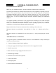
INSTALLATION Figure 1 6
NOTE: * SUPPLIED BY MANUFACTURER INTERIOR HORIZONTAL MINIMUM INSTALLATION NOTE: * NOTE: You may replace or cover this piece of material with a more decorative non-combustible material when the unit is installed. * SUPPLIED BY MANUFACTURER INTERIOR VERTICAL INSTALLATION WITH A MAXIMUM 42' RISE.
INSTALLATION GENERAL INFORMATION Remove the shipping carton. Make sure the unit is not damaged. Lift the top louver and remove three (3) nuts at the upper left, right, and center of the glass frame. Also, open louver at bottom and remove the three (3) nuts. Set the door aside and protect from inadvertent damage. Retain nuts for reassembly. Next, carefully remove the box of logs inside the appliance and set these aside. 1. Framing - Maintain dimensions for the appliance enclosure as illustrated in Figure 1.
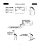
INSTALLATION EXTERIOR VENT LOCATIONS and RESTRICTIONS INSIDE CORNER DETAIL TERMINATION BOX, LOCATION CHART G V A H D E V L V B B C FIXED CLOSED V F N PE O V B B OPENABLE LE AB FIXED CLOSED V B J V A I M V K A A V = VENT TERMINAL A = AIR SUPPLY INLET A. Clearance above grade, veranda, porch, deck, or balcony (*12 inches (30cm) minimum) = AREA WHERE TERMINAL IS NOT PERMITTED H.
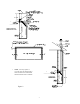
INSTALLATION NOTE: Direct-Vent (Balanced Flue) appliances are sensitive to vent configurations. Although this appliance may operate in some installations that fall outside this vent requirement chart, we cannot ensure its performance. MINIMUM - MAXIMUM VENT REQUIREMENTS 42' 42' 18' 18' VENTING MUST BE TERMINATED WITHIN SHADED AREA 12' 12' 6' 0' 0' 12' 4' MAX. * MIN. 6' 6' * MINIMUM DISTANCE FROM BEND OF 45° ELBOW TO FACE OF VENT CAP.
INSTALLATION VENT ASSEMBLY There are two basic types of installations approved with your model DV23ZC appliance. These are: Horizontal termination (See Figure 5) Vertical termination (See Figure 10) When planning your installation, refer to Figure 3 to ensure the length of your vent falls into the limits specified in Figure 3. Also consult page 9, “Exterior Vent Locations and Restrictions” regarding the placement of the vent terminal. HORIZONTAL TERMINATION 1. Set the gas appliance in its desired location.
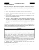
INSTALLATION HORIZONTAL TERMINATION (continued) NOTE: The horizontal run of vent must be level, or have a 1/4-inch rise for every 1 foot of run toward the termination. Never allow the vent to run downward. This could cause high temperatures and may present the possibility of a fire. A 2" clearance (airspace) MUST be maintained on all vent pipe. 4. With the pipe attached to the appliance adapter, slide the appliance into its correct location, and mark the wall for a 10" x 10" square hole.
INSTALLATION HORIZONTAL TERMINATION (continued) Note: The four wood screws provided should be replaced with appropriate fasteners for stucco, brick, concrete, or other types of siding. Venting termination shall not be recessed into a wall or siding. For structures with vinyl siding, a Vinyl Siding Standoff (Part 950) should be installed between the vent cap and the exterior wall. (See Figure 7.) Attach the Vinyl Siding Standoff to the Horizontal Vent Termination.
INSTALLATION VERTICAL TERMINATION 1. Set the gas appliance in the desired location. Drop a plumb bob down from the ceiling to the position of the appliance flue exit, and mark the location where the vent will penetrate the ceiling. Drill a small hole at this point. Next, drop a plumb bob from the roof to the hole previously drilled in the ceiling, and mark the spot where the vent will penetrate the roof. Determine if the ceiling joists, roof rafters or other framing will obstruct the venting system.
INSTALLATION VERTICAL TERMINATION (continued) 5. Slip the flashing over the Pipe Section(s) protruding through the roof. Secure the base of the Flashing to the roof with roofing nails. Ensure the roofing materials overlap the top edge of the Flashing as shown in Figure 12. Verify that you have at least the minimum clearance to combustibles at the roof line. Figure 12 6. Continue to add Pipe Sections until the height of the Vent Cap meets the minimum building code requirements described in Figure 13.
INSTALLATION VERTICAL TERMINATION (continued) NOTES: Use only 45 degree elbows. Use of 90 degree elbows is not allowed in vertical terminations. The 45 degree elbows offer less restriction to the flow of flue gases and intake air. For multi-story vertical installations, a Ceiling Firestop, (Simpson-Dura-Vent, Part 963) is required at the second floor, and any subsequent floors (Figure 14). The opening should be framed to 10" x 10" inside dimensions, in the same manner as shown in Figure 11.
INSTALLATION HIGH ALTITUDE This unit is approved in Canada for altitude from 0 to 2,000 ft. (0 to 600m) (Can 2.17-M90) with the main burner orifice supplied. For installations above 2,000 feet, follow current CAN/CGA-B149.1 and B149.2. In the USA refer to ANSI Z223.1 — latest edition, Appendix F, for resizing the orifice.
INSTALLATION GAS VALVE CONNECTION The gas control valve is located behind the lower grill. The control valve has a 3/8" NPT threaded inlet port. Secure all joints tightly using appropriate tools and sealing compound. Leak-check the installation with a soapy water solution or electronic leak detector. DO NOT USE OPEN FLAME FOR LEAK TEST.
OPERATION OPERATING INSTRUCTIONS Before operating this appliance, proceed through the following checklist. 1. Read and understand these instructions before operating this appliance. 2. Check that there are no gas leaks. If you smell gas do not attempt to light this appliance. 3. Verify that log placement is correct.
LIGHTING INSTRUCTIONS 1. STOP! Read the safety information on page 19. 2. Make sure manual shutoff valve is fully open. 3. Turn off all electrical power to the appliance. Open access door. ¬ 4. Turn control knob clockwise to the “OFF” position. CONTROL KNOB IN OUT PI L OT Figure 16 5. Wait five (5) minutes to clear out any gas. Then smell for gas, including near the floor. If you smell gas, STOP and follow “B” in the safety information on page 19! If you don’t smell gas, go to the next step.
NOTE: IF pilot goes out, repeat steps 4 through 10. Wait five (5) minutes before attempting to light pilot again. to “ON” position. 9. Turn control knob counterclockwise « 10. If using unit without wall thermostat place “Auto/Off/Manual” switch into the “Manual” position. If using wall thermostat place “Auto/Off/Manual” Switch into the “Auto” position and place thermostat to a setting higher than the room temperature. 11. Close access panel door. 12. Turn all electrical power on. 13.
Tabs shown unfolded LOG INSTALLATION 1. You must first unfold the left and right log support tabs. These tabs are folded down for shipping and must be unfolded before the rear log is put into place. 2. Place the rear log #1 on the back side of the burner base, flat side toward the rear of the firebox. 3. Take the middle log #2, Grasp it by both ends with ember burn out facing you. Position it between the front and rear burner in the middle of the burner supports. 4.
OPERATION PILOT AND FLAME Your appliance is equipped with a standing pilot to ensure proper burner ignition. It is visible by looking over the top of the middle log 6" from the right side. While igniting, the flame should impinge on the lighting port tube between the rear and middle burner, which ignites the front and rear burner. Figure 19 When burning, the flame on the middle log should be primarily blue, about 1" to 2" tall and causing a glowing effect on the face of the middle log.
OPTIONAL ROOM AIR BLOWER WIRING DIAGRAM Figure 20 CAUTION: LABEL ALL WIRES PRIOR TO DISCONNECTING WHEN SERVICING CONTROLS. WIRING ERRORS CAN CAUSE IMPROPER AND DANGEROUS OPERATION. VERIFY PROPER OPERATION AFTER SERVICING. THE APPLIANCE, WHEN INSTALLED, MUST BE ELECTRICALLY GROUNDED IN ACCORDANCE WITH LOCAL CODES, OR IN THE ABSENCE OF LOCAL CODES, WITH THE NATIONAL ELECTRICAL CODE, ANSI/NFPA70 OR THE CANADIAN ELECTRICAL CODE CSA C22.1. .
ACCESSORIES OR OPTIONS This unit is equipped with a millivolt system which enables you to choose from many of the convenient options available. 1. Remote control with built in room thermometer. 2. Wall Switch. 3. Wall Thermostat.
MAINTENANCE GENERAL MAINTENANCE Annual maintenance of the unit is required. We recommend that the following procedures be performed each year by your fireplace dealer. Clean all lint and dust build-up around the control valve and air shutter of the venturi. Inspect and clean with a vacuum cleaner around the venturi for any spider webs or lint accumulation. Remove logs and coals, and clean away any foreign matter (excessive lint from carpeting, bedding material, pet hair, household dust, etc.
SERVICING Repair and replacement work should only be done by a qualified service person. Always shut off the gas supply and make sure that heater is cool before beginning any service operation. Always check for gas leaks after servicing. REPLACEMENT PARTS A parts list with exploded view follows. Always include correct name, part number, and model number of the heater when ordering service parts. KEY# PART DESCRIPTION PART NUMBER 1. S.I.T. PILOT (L.P.) ASSEMBLY PE 199615 1. S.I.T.
REPLACEMENT PARTS Figure 22 16 28
ADDITIONAL REPLACEMENT PARTS PART DESCRIPTION PART NUMBER *MOTOR *RHEOSTAT *RHEOSTAT KNOB *THERMOSTAT 140 DEG.
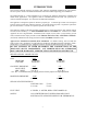
WARRANTY LIMITED FOUR YEAR WARRANTY FOR THE BUCK STOVE AND RELATED PRODUCTS PLEASE READ THIS WARRANTY CAREFULLY This warranty covers your new heating unit, so long as it is owned by the original purchaser, including optional and standard accessories purchased at the same time, subject to terms, limitations, and conditions herein set out.To make a claim under this warranty the Bill of Sale or Cancelled check must be presented.
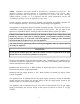
(D) All warranty repairs under this warranty must be performed by an authorized Buck Stove service representative. Repairs or attempted repairs by anyone other than an authorized service representative are not covered under this warranty. In addition, these unauthorized repairs may result in additional malfunctions, the correction of which is not covered by warranty. OTHER RIGHTS This warranty gives you specific legal rights, and you may also have other rights, which vary from state to state.