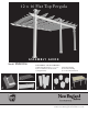
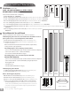
2 x 16 Flat Top Pergola A S S E M B LY G U I D E Model: Valencia OPTIONAL ACCESSORIES: A) Bolt Down Bracket Kit (3 for Pergola) D) Tall Base Molding B)12 x 16 Additional Shade Slat Kit E) Short Base Molding C) Pergola Planter F) 12 x 16 Canvas Weave Kit B C D A Ver 2.3-122116 E F www.newenglandarbors.
Ta b l e o f Co n t e n t s 12 x 16 Flat Top Pergola PAGE Introduction & Overview……………………………. . . . . . . . . . . . . . . . . . . . . . . . . . . . . . . . . . . . . . . . . . . . . . . .………. . . . . . 3 Pergola Materials Overview………………………. . . . . . . . . . . . . . . . . . . . . . . . . . . …. . . . . . . . . . . . . . . . . . . . . . . . . . . . . . . . . . . 4 Pergola Materials Breakdown………………………. . . . . . . . . . . . . . . . . . . . . . . . . . . . . . . . . . . . .…. . . . . . . . . . . . . . . . .
I n t r o d u c t i o n & O ve r v i e w (Valencia Pergola Shown) Getting Started First off, allow us to say thank you for the investment you have made in one of our fine pergola kits. This kit is designed to be assembled and installed ideally by two people with basic carpentry knowledge and tools. Do not attempt alone, especially during the installation stage.
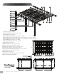
Valencia Pergola Materials Overview 13 15 16 1 2 3 4 6 9 10 8 11 12 17 5 7 18 14 1. Post Caps (3) - 5” Sq - 10699-1 2. Main Column Tops (3) - 5” x 5” x 32 5/8” - 10826 3. Post Trims (6) - 5” Sq - 10698-1 4. Rafter & Beam Decorative End Caps (13) - 2” x 6” - 10829 5. Main Support Beams with pre-drilled holes on top - Inner (2) - 2“ x 6” x 70“ - 11074 6. Main Support Beams with pre-drilled holes on top - Outer (4) - 2” x 6“ x 65 1/4” - 11075 7. Beam & Rafter Joiners (13) - 2“ x 6” - 10820 8.
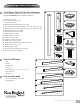
Valencia Pergola Materials Breakdown Check Boxes (Total of 5) for These Contents 8 2 1 In the event of missing or defective parts please call our customer service dept. at 1 800 282 9346 (Mon. to Fri. 8:00 AM to 4:00 PM EST). 1. Post Caps (3) - 10699-1 2. Main Column Tops (3) - 10826 3. Post Trims (6) - 10698-1 4. Rafter & Beam Decorative End Caps (13) - 10829 5. Main Support Beams with pre-drilled holes on top - Inner (2) - 11074 6.
Pergola Additional Materials List A BC E F DG H Hardware (in plastic bag) NOTE: WE HAVE INCLUDED 10% EXTRA SCREWS BEYOND WHAT IS IDENTIFIED BELOW. All Screws Included with this Kit are Self-Auguring. A. B. C. D. E. F. G.
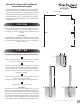
Wood Post Layout & Installation for attached Pergola This pergola can also be installed on a pre-existing wood or concrete surface using our bolt down bracket system with a 4x4 wood post (sold separate). See page eight for more details. 1 Overhead View 139.75 in. 355 cm. Post location and placement is the most critical step in the overall installation process. Please double check for the possibility of any underground utilities such as sprinkler, gas or telephone lines. STEP ONE 90 in. 228.6 cm.
1 * OPTIONAL STEP Wood Post Layout & Installation using Bolt Down Brackets for Concrete or Wood Surface for Attached Pergola 139 3/16 in 353.5 cm 1 Measure and mark out the location of the bolt down brackets using string or chalk line. Adjust string lines accordingly. The inside corner of the string lines will be the corner of the bottom flange. * Orientate brackets accordingly to reduce offset motion of posts.
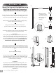
*Ensure that holes at top of column are orientated correctly for future beam and rafter placement. STEP THREE Vinyl Column Assembly & Installation Over Wood Posts * 1 Using the vinyl weld glue, insert the One Way 4”x4” Internal Wood Post Guide in the one end of the main column posts. This step is only applicable if your wood 4x4 post are embedded into the ground. If your pergola is going to be installed on wood or concrete surface, please dispose of these three pieces.
At this stage, the columns should be properly installed as per the following illustration, with the columns 88 1/2” in. (223.5 cm) apart. Critical: Note the opening direction of the holes on the top of the posts. 139 in. 353 cm. 88.5 in. 224.8 cm. 88.5 in. 224.8 cm. Note: The remainder of the instructions will omit the optional base trim mold kit.
STEP FOUR Main Support Beam Assembly (Wall Side) 1 Insert one 2x6x16 pressure treated wood into an inner main support beams followed by two joiners as illustrated. 2 Insert two outer main support beams until they both butt up tight inside the joiner. Center the 2x6x16 inside the main support beam so that the open space at each end is equal. Critical Note: Note the location of the pre-drilled holes on the top edge of the outer main support beams.
STEP FOUR 4 Attach and fasten the nine rafter hangers as shown. Align the top holes on the rafter hangers to those on top of the main support beams and fasten with two, 1 1/2” screws each. Secure each rafter hanger in place using two 1 1/2” screws through the pre-drilled holes as shown. 4 STEP FIVE Rafter Assembly 1 Insert one 2x6x12 pressure treated wood into an inner rafter section (75 3/8” long) followed by a rafter joiner. Make sure the wood is flush against the the edge of the inner rafter as shown.
STEP SIX Main Support Beam Assembly (Posts Side) Pre-drilled holes on top 1 With a helper, insert the second inner main support beam through the middle post assembly followed by a 2x6x16 pressure treated wood as shown. Note: Make sure the pre-drilled holes on the inner main support beam is facing up. 1 2 Add a joiner as shown and “thread” the pressure treated wood through an outer beam. Note the pre-drilled holes on the outer beam.
STEP SIX 4 4 Fasten the joiners to the main support beams with four 1 1/2 in screws as shown. 5 The main support beam should overhang the post by 4 1/4 in on both sides. 6 Secure the main support beam to the posts using eight, 4 in screws for each post in a rectangular pattern as shown. 7 Align the holes on the rafter brackets to the pre-drilled holes on the main support beam and fasten with two, 1 1/2” for each of the bracket.
STEP SEVEN Ledger Boards installation Using a helper and two ladders proceed to complete the following steps: 1 Mount the three 2x6 pressure treated wood boards (sold seTo locate the position of your wood beams; parate) on your wall surface. Please consult your local hardware A. Measure half way between the middle vinyl post store regarding methods of mounting. We recommend 11 lag B. Mark and draw a string line square to the wall. screws if mounting to a wood siding or concrete/brick anchor C.
STEP EIGHT Main Support Beams & Rafters Placement Using a helper and two ladders proceed to complete the following steps: 1 1 Mount the main support beam which has the rafter hangers onto the wood boards as shown. The top of the wood beam should be flush with the top of the pergola beam. Align the joiners to be between the 4” gaps between the wood boards mounted in the previous step. To fasten, use a minimum of eight 3½” lag screws through the main support beam and wood beam.
STEP NINE Fastening Decorative End Caps & Post Caps 1 Install decorative pergola end caps using vinyl weld. 2 Install the post caps using vinyl weld. 3 Final position your post trims. 2 1 To glue decorative end caps place: 1. Apply a generous amount of vinyl glue to the decorative end caps as shown. 2. Slide the decorative end caps into the beam/rafter and allow a few minutes for glue to cure. 3 To position post trim in place: 1. Slide the post trim down. 2.
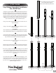
STEP TEN Shade Slat Assembly 1 Assemble shade slats by inserting the two joiners into the inner shade slat followed by the two outer shade slats. Push firmly until extrusion bottoms out inside joiner. No screws are necessary. Complete the assembly by gluing a decorative end cap at each end as shown. 1 Note: If you purchased the Additional Shade kit or Canvas Weave kit, please consult their respective instructions at this point.
STEP ELEVEN Shade Slats Installation The 7/8 x 3 shade slats are designed to be installed with 11” spacing between each slat. This spacing must be followed if you are planning to install the optional Canvas Weave Kit. 1 Note: Shade slats can re repositioned as needed to suit your application as there are no pre-drilled holes. Dry fit the shade slats first to ensure none of the shade slats interfere with the rafter joiners. Shade slats are designed to extend approximately 6 3/4” past the last rafter.