Accessories PRO 3.0 Sink and Faucet 48” 72” Slatwall Backsplash Kit 56” 48in, 56in, 72in Display Wall Shelf Sets 84” 16sqft.
Index Sink and Faucet 48in, 56in, 72in Display Wall Shelf Sets Slatwall Backsplash Kit 16sqft.
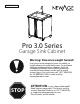
*. 1# " Pro 3.0 Series Garage Sink Cabinet Warning: Excessive weight hazard! Use two or more people to move, assemble, or install cabinets to avoid back injury. Do not leave children unattended near cabinets. High risk of tipping if cabinets are installed incorrectly: securely attach cabinets to the wall to avoid serious injury. For assistance, call 1.877.306.8930; for U.K 0800.031.4069: e-mail at info@ newageproducts.com.
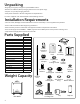
Unpacking • Begin by placing the package on a protected flat surface. • Remove all cardboard, foam packaging material and clear plastic bags. • Dispose / recycle all packaging materials. • Verify all the contents in the box and gather the required tools. See “Parts Supplied” and “Tools Needed” in the following sections Installation Requirements • For best results, NewAge recommends that this unit be installed by a licensed, professional plumber. • Please read instructions before beginning installation.
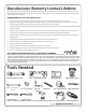
Manufacturer Warranty Limited Lifetime When this product is installed, operated and maintained according to the instructions attached to or furnished with the product, NewAge Products Inc. will replace the defective product or parts if the part fails as a result of defective materials or workmanship for the Lifetime of the product. NEWAGE PRODUCTS INC. WILL NOT PAY FOR: 1. Service calls to correct the installation of any NewAge products or to instruct you how to use or install them. 2.
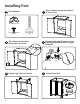
Installing Feet Parts Needed. 1 Open cabinet, remove any shelves or loose items. Align foot with edge of cabinet. Screw in 4 x foot attachment screws using #3 Phillips Bit 4X Cabinet Legs Foot Attachment Screws 4X Levelling Foot 2 Flip cabinet upside down, locate holes at corners. 3 4 Repeat step 3 for each corner. 5 4 Stand & level feet.
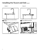
Installing the Faucet and Sink Parts Needed. Top Washer with Sealing Gasket Faucet Plastic Assembly Fastening Threaded Sleeve Reducer 2 1 Add top washer with sealing gasket to faucet assembly and insert braided hoses through faucet hole on top side of sink 3 Along the bottom side edges of the sink, insert four 4mm x 15mm bolts half way.
Installing the Faucet and Sink (cont.) Option 1 6 6 Tighten Screws to secure sink to cabinet.
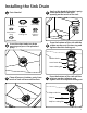
Installing the Sink Drain Parts Needed. Tailpiece Drain Locking Nut Drain Body Anti-Friction Ring Tailpiece Locking Nut Plastic Tailpiece Washer 1 Apply a thin bead of plumber’s putty to the perimeter of the drain opening on the inside of the sink. 3 From the bottom of the sink add the rubber washer, anti-friction ring and tighten the drain locking nut 4 -1/4” Rubber Washer 2 Insert the drain body into drain opening and press into plumber’s putty.
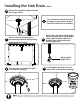
Installing the Sink Drain (cont.) 6 Attach the sink drain tailpiece to the drain pipe outlet For assistance connecting sink to plumbing system please contact your local contractor or plumber. 7 Access to water intake valves is provided by the back wall opening and bottom of cabinet. 8 Fasten the (red) hot water braided hose to the hot water intake angle valve, and the (blue) cold water braided hose to the cold water intake angle valve.
Securing Cabinets to Wall Note: Wall hanging brackets are not designed to support the weight of a loaded cabinet. Cabinets must be secured to the wall using supplied 1/4” x 2.5” lag screws. 1 Use stud finder to locate the studs and mark the wall with a pencil. 2 Gather parts. 4x Wall Screw (1/4” x 2.5”) 4x Wall Washer (1/4”) Sink Cabinet: 4 wall screws and 4 washers 3 Place cabinet tight against the wall. 6 Drill 4 wall screws and washers through perforated holes into studs.
Hanging Cabinets on Wall Lag Screw (1/4” x 2.5”) 2 Use stud finder to locate the studs and mark the wall with a pencil. 1 Parts Needed. Wall Washer (1/4”x0.9-in) Wall Bracket Planning the general position of cabinets. Step A. Determine the height off the ground you would like the base and locker cabinets to be and make a horizontal mark at this position. Step B. Next mark the width of each cabinet in the intended position and ensure the wall studs fall at least 1.
Hanging Cabinets on Wall (cont.) Planning the general position of cabinets. (cont.) Step C. Measuring up from the line marked in Step A, make a horizontal mark at the following heights where they intersect the wall stud marks to determine where the top of the cabinet will be (and where the hanging bracket will be installed). 1. Locker: Measure 80” vertically from base line and mark at stud locations. 2. Base: Measure 32.25” vertically from base line and mark at stud locations. 3.
Hanging Cabinets on Wall (cont.) 4 Hanging cabinets on wall. Align the top of the wall hanging brackets with the lines marked for the position of the top of the cabinets(Step C) and attach the brackets securely into the studs using the supplied lag bolts and washers. Note: It is possible to offset the bracket to one side or the other if the bracket is positioned close to the edge of the intended cabinet position by using the secondary hole positions on the bracket. C Base Cabinets 32.
Fastening Cabinets Parts Needed. Hex Bolt (1/4 x 5/8”) Washer (1/4”) 1 Note: Fasten additional cabinets to initial securely mounted cabinet. Align bolts, tighten lightly. 4 X EACH CABINET Lock Nut (1/4”) Note: Remove all drawers before fastening cabinets. Bolt each subsequent cabinet to the previous one using the supplied ¼” x 5/8” hex bolts and lock nuts provided in each base and wall cabinet. 2 Using a 12 inch magnetic level, align the cabinets and tighten all bolts.
Option of Using a Garden Hose 1 Unscew the aerator from faucet. 3 Attach garden hose by threading on to adaptor.
*. 1# " Série Pro 3.0 Cuve de Lavage avec cabinet AVERTISSEMENT: Risque de poids excessif! Déplacer, assembler ou installer les armoires et armoires-vestiaires avec l’aide de deux personnes ou plus. Dans le cas contraire, il pourrait en découler des blessures au dos ou autre. Ne pas laisser les enfants sans surveillance près des armoires. Risque élevé de basculement si les armoires ne sont pas installées correctement : Fixer solidement les armoires au mur pour éviter des blessures graves.
Déballage • Commencer par placer la boîte sur une surface plate recouverte. • Retirer tout le carton, le matériel d’emballage en mousse et les sacs en plastique transparent. • Mettre au rebus ou recycler tous les matériaux d’emballage. • Vérifier tout le contenu de la boîte et rassembler les outils nécessaires. Voir Pièces fournies et Outils nécessaires ci-dessous. Guides d’installation •Pour de meilleurs résultats, NewAge recommande que cette unité soit installée par un plombier professionnel autorisé.
Garantie limitée d’un an offerte par le fabricant Si ce produit a été installé, utilisé et entretenu conformément aux instructions jointes au produit, ou fournies avec celui-ci, NewAge Products Inc. remplacera les pièces ou articles défectueux si la défaillance de la pièce en question résulte d’un défaut de pièce ou de main-d’œuvre, et ce, pendant un an à compter de la date d’achat du produit. NEWAGE PRODUCTS INC. N’ASSUMERA PAS LES COÛTS SUIVANTS : 1.
Installation des pieds 1 Pièces nécessaires. Ouvrir l’armoire et retirer les étagères ou les objets en vrac. 4X Jambes de cabinet Foot Attachment Screws 4X Pied réglable (M10 x 65mm) 2 Retourner l’armoire et repérer les trous dans les coins. 3 4 Répéter l’étape 3 pour chaque coin. 5 18 Aligner le pied sur le bord de l’armoire. Visser4 vis à sécurités dans les trous ultilisant un tête de vis Philips #3 Remettre à l’endroit et niveler.
Installation du robinet et de l’évier 1 Pièces nécessaires. Ajouter le rondelle et le joint d’étanchéité. Insèrer les tuyau tressé dans le trous pour robinet. Rondelle Joint en d’étanchéité caoutchouc Assemblée de robinet 2 Douille de fixation en plastique Reducteur fileté Évier Tuyau tressé Par l’interieur de l’armoire, ajouter le joint d’étanchéité. Serrer ultilisant le douille de fixation plastique.
Installation du robinet et de l’évier Option 1 Option 2 6 7 20 Serrez les vis pour fixer l’évier à l’armoire. (CONT.) Déplacer l’armoire à la position.
Installation du drain d’évier Pièces nécessaires. Rallonge d’about Écrou de vidange Anneau d’about 4 -1/4” Rondelle à caoutchouc 1 Appliquer une petite quantité de mastic de plombier autour de l’ouverture du l’évier. 3 Installer la rondelle d’étanchéité en caoutchouc, l’anneau de friction, et le écrou de vidange par en dessous l’evier. Panier de vidange Rondelle en plastique Contre-écrou 2 Insèrer le panier de vidange dans l’ouverture de l’évier.
6 Fixez le cordon du drain de l’évier à la sortie du tuyau de vidange Pour l’assistance a brancher l’évier au système de plomberie, veuillez contacter votre entrepreneur local ou votre plombier. 7 Retirez les trous perforés sur le dos ou le bas de l’armoire pour assurer l’accès aux soupapes d’admission d’eau. 8 Attaches le tuyau tressé pour l’eau chaud (rouge) à la prise d’eau chaude. Attaches le tuyau pour l’eau froid(bleu) a la prise d’eau froid.
Remarque: Montages des armoires sur clouté mur 1 Utiliser le localisateur de montants pour repérer les montants et tracer une ligne sur la cloison avec un crayon. 2 Ne pas charger l’armoire sans avoir d’abord fixer au mur. Rassembler les pièces. Vis murales (¼” x 2½”) Rondelle murale (¼”) Sink Cabinet: 4 wall screws and 4 washers 3 Bien appuyer l’armoire contre le mur. 6 Percer 4 vis murales et rondelles dans les trous perforés des montants. 4 Aligner l’armoire sur les marques des montants.
Fixation des armoires au mur (facultatif) 1 Pièces nécessaires. Tire-fond (1/4 po x 2,5 po) 2 Utiliser le localisateur de montants pour repérer les montants et faire une ligne sur le mur avec un crayon. Support mural Planification de la position générale des armoires. Étape A. Déterminer la hauteur à laquelle vous aimeriez installer les armoires sur plancher et armoires-vestiaires et tracer une ligne horizontale à cet endroit. Étape B.
Fixation des armoires au mur (suite) Planification de la position générale des armoires (suite) Étape C. En mesurant à partir de la ligne faite à l’étape A, faire une marque horizontale à la hauteur à laquelle elle croise les marques du panneau mural pour déterminer la hauteur de l’armoire voulue (et l’endroit où installer le support). 1. Armoire-vestiaire : Mesurer une distance de 80 po à partir de la ligne de référence et faire une marque aux emplacements des montants. 2.
Fixation des armoires au mur (suite) 4 Fixation des armoires au mur. Aligner le dessus des supports d’accrochage sur les lignes identifiées pour la position du dessus des armoires (étape C) et fixer solidement les supports dans les montants à l’aide des tirefonds et des rondelles fournis. Remarque : Il est possible de contrebalancer le support vers un côté ou l’autre si celui-ci est installé près du bord de la position désirée pour l’armoire en utilisant les positions secondaires des trous sur le support.
Raccord des armoires Pièces nécessaires. 1 Raccorder les autres armoires à la première armoire solidement assemblée. Aligner les boulons, serrer légèrement. Boulon à tête hexagonale (1/4 po x 5/8 po) Rondelle (1/4 po) Remarque : X4 fois par cabinet Contre-écrou (1/4 po) Remarque : Retirer tous les tiroirs avant de raccorder les armoires ensemble. 2 Mettre à niveau les armoires et serrer tous les boulons.
Raccord de tuyau d’arrosage 1 Retirer l’aérateur du robinet.. 3 Une fois que l’adaptateur de tuyau a été fixé, fixer l’extrémité du tuyau d’arrosage au robinet. Tuyau d’arrosage Adaptateur Tuyau d’arrosage 28 2 Fixez l’adaptateur de tuyau d’arrosage à la fin du robinet.
IM-PB3.03A-02 Pro & Bold Series 3.0 48in, 56in, 72in Display Wall Shelf Sets Warning: Excessive weight hazard! Use two or more people to move, assemble or install shelving to avoid back or other injury. Do not leave children unattended near the shelving. High risk of injury if installed incorrectly: Follow instructions carefully and routinely inspect your system to ensure all components are fastened securely. For assistance, call 1.877.306.8930; for UK 0800.031.4069; e-mail at info@newageproducts.
Unpacking Thank you for purchasing a NewAge Product! • Begin by placing the package on a covered flat surface. Please give us a call or visit online if you have any questions. Call 1.877.306.8930; for UK 0800.031.4069; email at info@newageproducts.com • Remove all cardboard, packaging material and clear plastic bags. • Dispose / recycle all packaging materials. • Verify all the contents in the box and gather the required tools.
Tools Needed Tape Measure 3/16” Drill Bit Stud Finder Pencil Safety Glasses 7/16” & 1/2” Socket Wrench 7/16” socket Magnetic Leveler Cordless Power Drill Ladder Manufacturer Warranty Limited Lifetime When this product is installed, operated and maintained according to the instructions attached to or furnished with the product, NewAge Products Inc. will replace the defective product or parts if the part fails as a result of defective materials or workmanship for the Lifetime of the product.
Weight Capacity WARNING: Do not exceed the weight capacity of the wall shelves. Each Shelf has an evenly distributed weight capacity of 250lbs. Each Shelf must be secured between two Locker or Wall Cabinets and attached to the wall. 250lbs 250lbs Display Shelf Installation: Note: Cabinets must be installed before installing display shelves 1 Ensure there is 48in/56in/72in between the Wall Cabinets / Lockers depending on your shelf size.
3 Align the top of the shelf with the top of the Wall Cabinet / Locker and insert the 1/4” Hex bolt and washer through the mounting holes and tighten with a lock nut. Repeat to the opposite side. Note: Refer to Installation Tips for installing the top shelf upside down 4 Check and level before securing to Wall. 5 Using a stud finder locate the wall studs and mark the location to drill in the Wall Shelf slot holes. www.newageproducts.
6 Drill a pilot hole using a 3/16” drill bit. Using a 1/4” x 2-1/2” lag bolt, one 1/4” ID Fender Washer and a 7/16” socket, bolt the Wall Shelf into the Stud. Repeat for remaning studs and second shelf. Parts Needed: Lag Bolt Lag (1/4”dia Screw x 3”) (1/4” dia x 2-1/2”) Fender Washer 7/16” Socket (1/2” OD) 7 Using two M5 Phillips bolts, screw the Light Valance into the Wall Shelf hex rivet. Repeat for all remaning Light Valances.
SERIE PRO ET BOLD 3.0 System de Tablettes Murale - 48po, 56po, 72po ATTENTION: Risque de poids excessif! Utilisez deux personnes ou plus pour déplacer, assembler ou installer les étagères afin d'éviter tout risque de blessure au dos ou autre. Ne laissez pas les enfants sans surveillance près des étagères. Risque élevé de blessure en cas d'installation incorrecte: suivez les instructions avec soin et inspectez régulièrement votre système pour vous assurer que tous les composants sont bien fixés.
Déballage Merci d’avoir acheté un produit NewAge! • Commencez par placer l’emballage sur une surface plane et couverte. • Enlevez tout le carton, le matériel d’emballage et les sacs en plastique transparents. • Éliminer / recycler tous les matériaux d’emballage. • Vérifiez tout le contenu de la boîte et rassemblez les outils nécessaires. S’il vous plaît appelez-nous ou visitez en ligne si vous avez des questions. Composez le 1.877.306.8930; pour UK 0800.031.4069; email à info@newageproducts.
Les outils nécessaires Ruban à measurer Foret de 3/16” Localisateur de montants Crayon Lunettes de protection 7/16” & 1/2” Clé à douille 7/16” Douille Niveau magnétique Perceuse-visseuse électrique Échelle Garantie à vie limitée du fabricant Lorsque ce produit est installé, utilisé et entretenu conformément aux instructions ci-jointes ou fournies avec le produit, NewAge Products Inc.
Capacité de poids Attention: Ne dépassez pas la capacité de poids des étagères murales. Chaque étagère a une capacité de poids uniformément répartie de 250 lb. Chaque étagère doit être fixée entre deux armoires vestiaires ou murales et fixée au mur.
3 Alignez le haut de l’étagère avec le haut de l’armoire murale / casier et insérez le boulon hexagonal 1/4 ”et la rondelle dans les trous de montage et serrez à l’aide d’un écrou de blocage. Répétez pour le côté opposé. Attention: Reportez-vous aux conseils d’installation pour installer la tablette supérieure à l’envers 4 Vérifiez et nivelez-le avant de le fixer au mur.
6 Percez un avant-trou avec un foret de 3/16 ”. En utilisant un tire-fond de 1/4 ”x 2-1 / 2”, une rondelle pare-choc de 1/4 ”et une douille de 7/16”, boulonnez la tablette murale dans le montant. Répétez cette procédure pour les montants restants et la deuxième étagère. Pièces nécessaires: LagVis Bolt (1/4”dia x 3”) Tire-fond (1/4” dia x 2-1/2”) Rondelle pare-choc Douille 7/16” (1/2” OD) 7 À l’aide de deux boulons Phillips M5, vissez la cantonnière dans le rivet hexagonal de l’étagère murale.
*. 1# " Bold and Performance 48” Pro and Performance Plus 72” 56” Slatwall Backsplash Kit WARNING: Excessive weight hazard! ! Use two or more people to move, assemble or install slatwall backsplash to avoid back or other injury. Do not leave children unattended near backsplash. High risk of injury if installed incorrectly: Follow instructions carefully and routinely inspect your system to ensure all components are fastened securely. For assistance, call 1.877.306.8930; for U.K 0800.031.
Index Tools Needed/ Weight Capacity Warranty Parts Supplied Installation Options for Cabinets/ Hanging on Studded Wall Installing Backsplash for Fixed Cabinets Installing Backsplash with Mobile System Installing Backsplash without Cabinets Unpacking • • • • Begin by placing the package on a covered flat surface. Remove all cardboard, foam packaging material and clear plastic bags. Dispose / recycle all packaging materials. Verify all the contents in the box and gather the required tools.
Tools Needed 1 x 12” MagneticLevel 1 x Cordless Power Drill 1 x #2 Phillips head screwdriver 1 x Stud Finder 1 x Tape Measure 1 x #2 Phillips Bit 1 x Pencil 1x 3 mm or 1/8” Drill Bit 1 x Hammer Drill 1 x Masonry Bit [optional for masonry] Weight Capacity 75lbs Per Square Foot 75lbs Works with Most Standard 3in On-Centre Slatwall Hooks www.newageproducts.
Manufacturer Warranty Limited Lifetime When this product is installed, operated and maintained according to the instructions attached to or furnished with the product, NewAge Products Inc. will replace the defective product or parts if the part fails as a result of defective materials or workmanship for the Lifetime of the product. NEWAGE PRODUCTS INC. WILL NOT PAY FOR: 1. Service calls to correct the installation of any NewAge products or to instruct you how to use or install them. 2.
Parts Supplied 48” Bold / Performance 72” Bold / Performance 56” Pro / Performance Plus 1 84” Pro / Performance Plus 1 Fixed Bottom 1 1 Slatwall Section 3 3 3 3 Top Cover Strip 1 1 1 1 Mobile Bottoms 0 0 1 1 Mobile Side Covers 0 0 2 2 #8 Philips pan head screw 2in long 18 26 18 26 Bold / Performance Slatwall Backsplash Parts Top Magnet Cover Slatwall Sections Fixed Bottom Pro/ Performance Plus Slatwall Backsplash Parts Top Cover Strip Mobile Sides Slatwall Sections Fixe
Hanging Slatwall Backsplash on Studded Wall 1 Use stud finder to locate the studs and mark the wall with a pencil 3 Determine installation option based on your cabinet series and cabinet configuration 2 Repeat step 1 for each stud Fixed Slatwall Backsplash Mobile Slatwall Backsplash For Cabinets on Feet Continue to Page 7 For Performance Plus Sets on Casters with Mobile Spacer Kit Continue to Page 8 Note.
Installing Backsplash for Fixed Cabinets 4 Place fixed bottom strip tight against the wall and the top of the worktop. If your cabinet set does not have lower cabinets with a worktop proceed to page 9 6 Interlock bottom of Slatwall section with the top of fixed bottom strip. Repeat step 5 to securely fasten “Slatwall Section”. 8 Interlock Top Magnet Cover on top of the slatwall section and secure in position with magnets.
Installing Backsplash with Mobile System 4 Align the side ends of the slatwall with the side ends of the worktop 5 6 Interlock bottom of Slatwall Section with the top of Mobile Bottom and follow steps 5 to 8 on page 7. 7 8 Remove protective adhesive film on the back of Mobile Side Covers. Press firmly to adhere to the wall. Masonry. • • • • 8 Ensure that the Mobile Bottom is tight against the wall and the top of the worktop.
Installing Backsplash Without Cabinets 4 5 Mark the bottom position of the slatwall backsplash by measuring down from the bottom of the wall cabinets. The distance is dependent on the cabinet series and installation type, as shown in the table to the right.
*. 1# " Bold et Performance Pro et Performance Plus 56 po 48 po 84 po 72 po Ensemble des Panneaux Muraux ! AVERTISSEMENT: RISQUE DE POIDS EXCESSIF! Déplacer, assembler ou installer les panneau mural avec l’aide de deux personnes ou plus pour éviter le dos ou d’autres blessures. Risque élevé de blessure si installé incorrectement: Suivez attentivement les instructions et inspectez régulièrement votre système pour vous assurer que tous les composants sont bien fixés.
Index Outils nécessaires/ Capacités poids Garantie Pièces fournies Options d’installation pour le Cabinet/ Suspendu sur le mur clouté Installation des panneaux mural pour les armoires fixes Installation des panneaux mural avec un système mobile Installation des panneaux murales sans armoires de plancher Déballage • Commencer par placer la boîte sur une surface plate recouverte. • Retirer tout le carton, le matériel d’emballage en mousse et les sacs en plastique transparent.
Les outils nécessaires 1 x vérin magnétique de 12 po 1 x perceuse mecanique sans fil 1 x localisateur de montants 1 x Crayon 1 x ruban à measurer 1 x marteau perforateur 1 x Tête Phillips n 2 (facultative) 1 x foret à maçonerrie facultatif pour la maçonnerie 1 x tournevis #2 Philips 1 x Foret de 3 mm ou 1/8 po Capacité de poids 75 lb par pied carré 75lbs Fonctionne avec la plupart des panneaux murals sur le dessus standard 3 po au centre www.newageproducts.
Garantie à vie limitée du fabricant Lorsque ce produit est installé, utilisé et entretenu conformément aux instructions ci-jointes ou fournies avec le produit, NewAge Products Inc. remplacera les pièces ou le produit défectueux advenant que ceux-ci découlent d’un défaut de matériel ou de fabrication pendant la durée de vie du produit. NEWAGE PRODUCTS INC. N’ASSUMERA PAS LES COÛTS SUIVANTS : 1.
Pièces fournies Pro / Bold / Performance Bold / Performance Performance Plus 48 po 72 po 56 po Pro / Performance Plus 84 po Moulure pour panneau mural aimant 1 1 1 1 Section de panneau 3 3 3 3 Section de panneau inférieur 1 1 1 1 Moulure pour panneau inferieur pour le systeme mobile 0 0 1 1 0 0 2 2 18 26 18 26 Moulure latérales pour le système mobile Vis a tete bombée #8 Philips - longeur 2 po Pièces pour les panneaux murals Bold/ Performance Moulure pour panneau mural aimant
Accrochant les panneaux murals sur un mur gypse avec des montants en bois 1 Utilisez un détecteur de montants pour localiser les montants et marquer le mur avec un crayon 3 Déterminer l’option d’installation en fonction de votre armoire et de votre armoire configuration. Panneau murale fixée 2 Répétez l’étape 1 pour chaque montants en bois.
Installation des panneaux mural pour les armoires fixes 4 Placer le section de panneau inférieure contre le mur et dessus le plan de travail. Si votre meuble n’a pas d’armoires en bas avec un plan de travail, passez à la page 9 6 S’imbriquez le bas de la premier panneau avec le dessus de la section inférieure fixe. Répétez l’étape 5 pour fixer solidement le panneau mural. 8 S’imbriquez le moulure aimant sur le dessus de la panneau et sécuriser en position avec des aimants.
Installation des panneaux mural avec un système mobile 4 6 Alignez le moulure pour panneau mural inférieur pour le système mobile avec les cotés du plan de travail. S’imbriquez le bas du panneau mural avec le haut du moulure pour le système mobile et suivez les étapes 5 à 8 à la page 7. 5 Retirez le film adhésif de protection à l’arrière des pieces de panneau latérals. Appuyez fermement pour adhérer au mur. 7 Maçonnerie.
Installation des panneaux murales sans armoires de plancher 4 Mesurez et faites une marque depuis le bas des armoires murales le correcte distance. La distance dépend de la série d’armoires et le type d’installation, comme indiqué dans le tableau à droite.
*. 1# " 16sqft. Diamond Plate Slatwall Kit WARNING: Excessive weight hazard! ! Use two or more people to move, assemble or install slatwall to avoid back or other injury. Do not leave children unattended near slatwall. High risk of injury if installed incorrectly: Follow instructions carefully and routinely inspect your system to ensure all components are fastened securely. For assistance, call 1.877.306.8930; for U.K 0800.031.4069; e-mail at info@newageproducts.com.
Index Tools Needed/ Weight Capacity Warranty Parts Supplied Preparing for Installation Installing Slatwall 3 4 5 6 7-9 Unpacking • • • • Begin by placing the package on a covered flat surface. Remove all cardboard, foam packaging material and clear plastic bags. Dispose / recycle all packaging materials. Verify all the contents in the box and gather the required tools. See “Tools Needed”, and “Parts Supplied” list.
Tools Needed 1 x 12” MagneticLevel 1 x Cordless Power Drill 1 x #2 Phillips head screwdriver 1 x Stud Finder 1 x Tape Measure 1 x #2 Phillips Bit 1 x Pencil 1x 3 mm or 1/8” Drill Bit 1 x Hammer Drill 1 x Masonry Bit [optional for masonry] Weight Capacity 75lbs 75lbs Per Square Foot evenly distributed when securely mounted to wood joist or support capable of supporting such a load. Works with Most Standard 3in On-Centre Slatwall Hooks www.newageproducts.
Manufacturer Warranty Limited Lifetime When this product is installed, operated and maintained according to the instructions attached to or furnished with the product, NewAge Products Inc. will replace the defective product or parts if the part fails as a result of defective materials or workmanship for the Lifetime of the product. NEWAGE PRODUCTS INC. WILL NOT PAY FOR: 1. Service calls to correct the installation of any NewAge products or to instruct you how to use or install them. 2.
Parts Supplied 16sqft. Diamond Plate Slatwall Kit Bottom Strip 2 Slatwall Section 7 Top Cover Strip 2 Side Cover 4 Plastic Hole Covers 8 #8 Philips pan head screw 2in long 36 When installing a 4x4ft configuration, you will have the following pieces left over: x1 Top Cover Strip x1 Bottom Strip When installing a 2x8ft configuration, you will have the following pieces left over: x1 Slatwall Section 16sqft.
Preparing for Installation 1 Determine your setup. A. For a 4x4ft slatwall configuration, measure 48.25in down from the intended top of slatwall and mark a level line. B. For a 2x8ft slatwall configuration, measure 24.25in down from the intended top of slatwall and mark a level line. Recommended guidelines shown below: Recommended guidelines shown below: 24.25 inches 48.
Installing Slatwall 3 Place bottom strip tight against the wall aligning it to your marked level line. 4 Pre-drill 3mm (1/8”) holes into each stud then fasten slatwall section to each wood stud with screws provided. Recommended Heights: 4x4ft : 24-30 inches 2x8ft: 48 inches 5 Interlock bottom of Slatwall section with the top of bottom strip. Repeat step 5 to securely fasten “Slatwall Section”. 7 Interlock Top Magnet Cover on top of the slatwall section and secure in position with magnets.
8 10 Remove the film on the adhesive from the side cover. Press firmly on the adhesive to secure the cover strip in place 9 11 Align one side cover to the top slatwall panels while aligning the next cover to the bottom panels. The adhesive side will be applied to the front of the slatwall panels. Add the plastic hole covers to the top and bottom of the side covers. Repeat steps 8 to 10 for the opposite end.
Installing Multiple Slatwalls Together 1 Install first slatwall section following steps 1-10. 2 Measure and mark a vertical line 4mm’s (1/8in) away from the side cover strip and a second line levelled with the bottom of the installed slatwall. 3 Place fixed bottom strip tight against the wall aligning it to your marked lines. 4 Install remaining slatwall sections, top and side covers following step 4 - 11 on pages 7 and 8.
*. 1# " Kit de panneaux murals à plaque de diamant 16 pieds carrés ! AVERTISSEMENT: RISQUE DE POIDS EXCESSIF! Déplacer, assembler ou installer les panneau mural avec l’aide de deux personnes ou plus pour éviter le dos ou d’autres blessures. Risque élevé de blessure si installé incorrectement: Suivez attentivement les instructions et inspectez régulièrement votre système pour vous assurer que tous les composants sont bien fixés.Pour obtenir de l’aide, composer le 1.877.306.8930; au R.-U.
Index Outils nécessaires/ Capacités poids 3 4 5 6 7-9 Garantie Pièces fournies Préparation à l’installation Installation des panneaux murales Déballage • Commencer par placer la boîte sur une surface plate recouverte. • Retirer tout le carton, le matériel d’emballage en mousse et les sacs en plastique transparent. • Mettre au rebus ou recycler tous les matériaux d’emballage. • Vérifier tout le contenu de la boîte et rassembler les outils nécessaires.
Les outils nécessaires 1 x vérin magnétique de 12 po 1 x perceuse mecanique sans fil 1 x localisateur de montants 1 x Crayon 1 x ruban à measurer 1 x marteau perforateur 1 x Tête Phillips n 2 (facultative) 1 x foret à maçonerrie facultatif pour la maçonnerie 1 x tournevis #2 Philips 1 x Foret de 3 mm ou 1/8 po Capacité de poids 75 lb par pied carré répartis uniformément lorsque fixés solidement à les poteaux d’un mur en bois ou à un support capable de supporter une telle charge.
Garantie à vie limitée du fabricant Lorsque ce produit est installé, utilisé et entretenu conformément aux instructions ci-jointes ou fournies avec le produit, NewAge Products Inc. remplacera les pièces ou le produit défectueux advenant que ceux-ci découlent d’un défaut de matériel ou de fabrication pendant la durée de vie du produit. NEWAGE PRODUCTS INC. N’ASSUMERA PAS LES COÛTS SUIVANTS : 1.
Pièces fournies Kit de panneau mural à plaque de diamant 16 pieds carrés Bande inférieure 2 Panneau mural 7 Bande de couverture supérieure Couvercle latéral 2 Cache-vis 8 Tête cylindrique Phillips n° 8 de 2 po de long Lors de l’installation d’une configuration 4x4ft, vous aurez les pièces suivantes qui reste: x1 Bande de couverture supérieure x1 Bande inférieure 4 36 Lors de l’installation d’une configuration 2x8ft, vous aurez les pièces suivantes qui reste: x1 Panneaux Mural Pièces pour les p
Préparation pour l’installation 1 Déterminez votre configuration. A. Pour une configuration de panneau mural de B. Pour une configuration de slatwall de 2 x 8 4 x 4 pi, mesurez 48,25 pouces vers le bas depuis la partie supérieure de la paroi de slatwall prévue et marquez une ligne de niveau. Directives recommandées illustrées ci-dessous: pieds, mesurez 24,25 pouces vers le bas depuis le dessus prévu de la paroi de la plaque et marquez une ligne de niveau.
Installation des panneaux murals 3 Placez la bande inférieure fixe contre le mur en l’alignant sur votre ligne de niveau marquée. Percez des trous de 3 mm (1/8 po) dans chaque montant, puis fixez la section de panneau à chaque poteau de bois avec les vis fournies. 4 Hauteurs recommandées: 4x4pi: 24-30 pouces 2x8pi: 48 pouces 5 7 Verrouillez le bas de la section de panneau avec le haut de la bande inférieure fixe. Répétez l’étape 5 pour fixer solidement chaque section de panneau.
8 Retirez le film sur l’adhésif du couvercle latéral. 10 Appuyez fermement sur la couverture pour fixer la bande d’adhésif en place. 9 11 Alignez un des panneaux latéraux sur les panneaux latéraux supérieurs tout en alignant le capot suivant sur les panneaux inférieurs. Le côté adhésif sera appliqué à l’avant des panneaux de murals Ajouter les couvercles de trous en plastique au haut et au bas des couvercles latéraux. Répétez les étapes 8 à 10 pour l’extrémité opposée.
Installation de plusieurs panneaux ensemble 1 Installez la première section de slatwall en suivant les étapes 1 à 10. 2 3 Placez la bande inférieure fixe contre le mur en l’alignant sur les lignes tracées. 4 Mesurez et tracez une ligne verticale à 4 mm (1/8 po) de la bande de couverture latérale et une deuxième ligne au niveau du bas du mur à lattes installé.
IM-PB3.13A-01 Slatwall 12pc, 20pc, 40pc Multi-Hook Accessory Kit Warning: Excessive weight hazard! Use two or more people to move, assemble or install slatwall to avoid back or other injury. Do not leave children unattended near slatwall or accessories. High risk of injury if installed incorrectly: Follow instructions carefully and routinely inspect your system to ensure all components are fastened securely. For assistance, call 1.877.306.8930; for UK 0800.031.4069; e-mail at info@newageproducts.
Unpacking Thank you for purchasing a NewAge Product! • Begin by placing the package on a covered flat surface. Please give us a call or visit online if you have any questions. Call 1.877.306.8930; for UK 0800.031.4069; email at info@newageproducts.com • Remove all cardboard, packaging material and clear plastic bags. • Dispose / recycle all packaging materials. • Verify all the contents in the box and gather the required tools.
Weight Capacity Warning Single Hook 15lbs Double Hook 30lbs 4” Loop Hook 30lbs Deep Utility Hook 30lbs Vertical Bike Hook 1 Bike - MAX30lbs Mesh Basket 30lbs Shallow Basket 30lbs Magnetic Tool Bar 5lbs / Tool WARNING: Do not exceed the weight capacity of the slatwall panels.
Hook Accessory Installation WARNING: Only install Accessory Hooks onto securely mounted Slatwalls Standard Installation: 1 Once the Slatwall is installed; install the hook by guiding the top lip into the desired channel. 2 Seat the hook by inserting and resting the lower lip into the channel below. Note: Do not attempt to install accessories upside down. Ensure accessories are securely installed before mounting objects. 4 www.newageproducts.
Parts Bin Accessory Installation WARNING: Only install Accessory Hooks onto securely mounted Slatwalls Standard Installation: 1 Once the Slatwall is installed; install the parts bin by guiding the top lip into the desired channel. 2 Seat the parts bin by inserting and firmly pressing the top lip onto the Slatwall channel. Note: Slatwall accessories will not function properly if installed upside down. Ensure the accessories are properly installed before mounting objects. www.newageproducts.
Bike Hook Accessory Installation WARNING: Only install Accessory Hooks onto securely mounted Slatwalls Standard Installation: 1 After properly installing the Slatwall and Bike Hook, guide the bikes front wheel into the hook. 2 Slowly lower the bike as it begins to secure itself on the wall. 6 www.newageproducts.
IM-PB3.13A-01 Panneau Mural 12pc, 20pc, 40pc kit d'accessoires multi-crochet AVERTISSEMENT: RISQUE DE POIDS EXCESSIF! Déplacer, assembler ou installer les panneaux mural avec l’aide de deux personnes ou plus. Ne pas laisser les enfants sans surveillance près du panneau. Risque élevé de blessure si installé incorrectement: Suivez attentivement les instructions et inspectez régulièrement votre système pour vous assurer que tous les composants sont bien fixés. Pour obtenir de l’aide, composer le 1.877.306.
Déballage Merci d’avoir acheté un produit NewAge! Enlever les cartons, le matériel d’emballage en mousse et les sacs en plastique transparents. Jeter/recycler tous les matériaux d’emballage. Vérifier le contenu de la boîte et rassembler les outils requis. Voir la liste des(Pièces fournis) et des (Outils nécessaires) ci-après. Veuillez nous appeler ou consulter notre site Web si vous avez la moindre question. Composer le 1.877.306.8930; au R.-U., composer le 0800.031.
Avertissement de capacité de poids Crochet 15lb Crochet de bicyclette vertical un vélo - MAX30lb Crochet Double 30lb Panier à maille 30lb Crochet fermé 30lb Crochet utilitaire 30lb Panier 30lb Barre d’outils magnétique 5lb/ Tool WARNING: Ne dépassez pas la capacité de poids des panneaux mural rainurés.
Installation des crochets Installation standard: ATTENTION: Installer seulement les crochets d’accessoires, sur les panneau mural solidement monté 1 Après l’installation du panneau mural,installer le crochet en guidant la lèvre supérieure dans le rainure. 2 Enfermer le crochet en insérant et en appuyant la lèvre inférieure dans le rainure ci-dessous. Remarque: N’essayez pas d’installer les accessoires à l’envers. Assurez-vous que les accessoires sont bien installés avant de monter les objets 10 www.
Installation du casier de rangement Installation Standard: ATTENTION: Installer seulement les crochets d’accessoires, sur les panneau mural solidement monté 1 Après l’installation du panneau mural, Installez le casier de rangement en guidant la lèvre supérieure dans le rainure.
Installation de crochet de bicyclette Installation Standard: ATTENTION: Installer seulement les crochets d’accessoires, sur les panneau mural solidement monté 1 Après avoir correctement installé le panneau murale et le crochet du bicyclette, guidez la roue avant du bicyclette dans le crochet. 2 Abaissez lentement le bicyclette pour se fixer sur le mur. 12 www.newageproducts.