RODS-L / RODS-L-F Operating Mamual
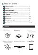
Table of Contents I Table of Contents ........................................................ 1 II Contents ...................................................................... 1 III 2 IV ............... 3 V VI Radar Sensor .............................................................. 4~5 VII Display units ............................................................... 6~7 8 VIII IX II Dimension ..................................................................
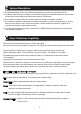
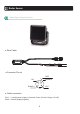
III System Description ● The Smallest Radar Sensor Active Blind Spot Detection System for Light-Duty Vehicle. ● The Radar Object Detection System uses FMCW (frequency modulated continuous wave) radar technology to detect stationary objects and people in blind spots. ● This advanced system alerts the operator with both visual and audible warnings.
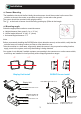
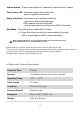
V Installation ◈ Sensor Mounting The installation site should be flat. Ideally the radar sensor should be mounted on the rear of the vehicles as close to the center as possible at roughly 1 meter above the ground. The sensor should be mounted in the upright position. The “↑“ on the back of sensor should be facing pointing top (Refer to the image) ◈ Mounting angle Select the appropriate location to mount the sensor. a. Height tolerance (from ground); 1m +/- 0.3 m) b.
VI Radar Sensor Radar Object Detection Sensor ● Rear Cable VCC GND ● Connector Pin out GND 5 NC 3 RS485-B 2 4 1 RS485-A VCC ● Cable connection Red : + Vehicle power supply or Reverse Power (3A fuse: Range +9~24V) Black : Ground (Supply negative) 4
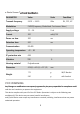
● Radar Sensor T PARAMETER Value Units Condition Transmit frequency 24.05 ~ 24.20 GHz EU, FCC, KC Modulation FMCW(Frequency Modulated Continuous Wave ) Supply voltage 12 ~ 24 V dc Current 300 mA@12V Power on time 300 ms Detection time 200 ms Communication RS-485 Operating temperature -40 ~ 85 IP protection rate 69K Vibration TBD Housing material Polycarbonate Dimension 43.6(H) x 43.6(L) x 33.
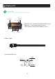
VII Display units Display units Dimmer button Volume button Power status LED ◆ LED # 5,4,& 3 are flashing (Furthest Detection zone 3) ◆ LED # 5 ~ 2 are flashing (Detection zone 2) ◆ All LEDs are flashing (Closest Detection zone 1) Range indication Mode 3 (LED #3) Mode 1 (LED #5) (LED #1) ● Rear Cable ● Connector Pin out GND 5 RS485-B 2 NC 3 1 4 VCC RS485-A 6
Volume button : Press volume button for 3 seconds to switch silence (3 steps) Power Status LED : Illuminates green continuously after power is applied to the system Range Indications : Illuminates to give operator a distance zone to the closest detected object. LED’s operate from the left to right, with a closer object resulting in more LED’s illuminated. Dim Button : Press Dim button to adjust LED (2 steps) (1) Press Dim button to verify the current mode for 3 seconds.
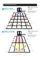
VIII Radar Detection Zone Mode .: 4.3(W) X 4.0(L) meter (Detection zone 3) RODS-L MODE Radar sensor Test Conditions Radar sensor (Height 1.0 meter) Test Person : 1.8meter tall. ZONE 1 1M ZONE 2 2M 3M ZONE 3 4M 5M 1 A ea → 1㎡ Mode .: 2.35(W) X 2(L) meter RODS-L-F MODE (Detection zone 3) Radar sensor Test Conditions Radar sensor (Height 1.0 meter) Test Person : 1.8meter tall.
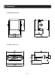
IX Dimension ● Radar Sensor (mm) ● Display units (mm) 9
● Radar Bracket (mm) ● Display Bracket (mm) 10
WARNING RISK OF ELECTRIC SHOCK DO NOT OPEN To reduce the risk of electric shock do not remove cover(or back) No user serviceable parts inside. Refer servicing to qualified service personnel. The lightning flash with arrowhead symbol,within an equilateral triangle,is intended to alert the user to the presence of uninsulated "dangerous voltage" within the product's enclosure that may be of sufficient magnitude to constitute a risk of electric shock to persons.