
Datasheet


1
NIC COMPONENTS CORP. www.niccomp.com www.lowESR.com www.RFpassives.com www.SMTmagnetics.com
®
Specifi cations are subject to change
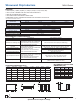
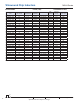
COMPONENT DIMENSIONS (mm):
Type Case Size
A max. B max. C max. D typ. E typ. F typ.
NIN-HK 0402
1.19 0.64 0.66 0.20 0.523 0.215
NIN-HJ 0603
1.80 1.12 1.02
0.38
0.76 0.33
NIN-HD 0805
2.29 1.68 1.55
0.51
1.27 0.50
NIN-HC 1008
2.92 2.79 2.29 0.51 2.00 0.50
NIN-HE 1206 3.56 2.16 1.52 .051 1.60 0.50
NIN-HA 1210 3.65 2.95 2.70 0.51 2.10 .050
NIN-HB 1812 4.95 3.81 3.43 1.78 2.90 .058
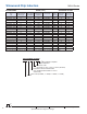
Type
H typ. I typ. J typ.
NIN-HK
0.65 0.35 0.50
NIN-HJ
1.02 0.64 0.64
NIN-HD
1.78 1.02 0.76
NIN-HC
2.54 1.02 1.27
NIN-HE 1.93 1.02 1.78
NIN-HA 3.02 1.02 1.78
NIN-HB 3.05 1.14 3.00
RECOMMEND LAND PATTERN
DIMENSIONS (mm)
Wirewound Chip Inductors
NIN-H Series
• SIZES K(0402), J (0603), D (0805), C (1008), E (1206), A (1210) and B (1812)
• HIGH Q, HIGH CURRENT AND HIGH SRF CHARACTERISTICS
• REFLOW SOLDERING APPLICABLE
• HIGH INDUCTANCE AVAILABLE IN SMALL SIZE
• EMBOSSED PLASTIC CARRIER PACKAGING FOR AUTOMATIC PICK-PLACE*
*0402 PUNCHED CARDBOARD CARRIER
FEATURES
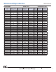
ENVIRONMENTAL CHARACTERISTICS
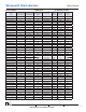
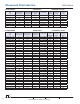
Specifi cations
Case Size Code
0402 (K) 0603 (J) 0805 (D) 1008 (C)
Inductance Range 1.8nH ~ 120nH 1.6nH ~ 470nH
2.2nH ~ 1.0μH 4.7nH ~ 8.2μH
Inductance Tolerance See Product Standard Values Tables
Operating Temperature Range
-40°C ~ +125°C
Test Specifi cations Test Method & Condition
Solderability 75% Min. Coverage After 3 sec. dip in +230°C soldering pot (post fl ux)
Resistance to Soldering Heat
(1) No evidence of damage
(2) Inductance change ±5% of initial value
(3) Q factor within ±10% of initial value
(±20% for 0402 & 0603 case sizes)
After 5 seconds at +260°C (with pre-conditioning)
Humidity
(1) No evidence of damage
(2) Inductance change ±5% of initial value
(±10% for 0402 case size)
(3) Q factor within ±10% of initial value
(±20% for 0402 & 0603 case sizes)
After 500 hours at 60°C and 90 ~ 95% RH
(0402 case size - after 96 hours 50°C and 90 ~ 95% RH)
Low Frequency Vibration After 2 hrs per axis, 10 ~ 55Hz, 1.5mm amplitude
Thermal Shock
After 100 cycles (10 cycles 0402) at -40°C and +125°C
(30 minutes at each temperature)
Low Temperature Storage After 500 hrs at -40°C
High Temperature Load Life
(1) No evidence of damage
(2) Inductance change ±10% of initial value
(±20% for 0402 case size)
(3) Q factor within ±10% of initial value
(±20% for 0402 & 0603 case sizes)
After 500 hrs at +125°C with rated DC current
(0402 case size - after 1,000 hrs at +85°C)
Humidity Load Life No evidence of short or open circuit
After 500 hrs at 60°C with 90 ~ 95% RH with rated DC current
(0402 case size- 1,000 hrs at +40°C)
J
I
H
C
D
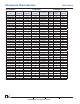
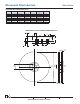
Specifi cations
1206 (E) 1210 (A) 1812 (B)
Inductance Range
3.3nH ~ 1.2μH 3.9nH ~ 8.6μH 1.0μH ~ 33μH
Inductance Tolerance See Product Standard Values Tables
Operating Temperature Range -40°C ~ +125°C
F
F
E
A
B