
Datasheet


2
NIC COMPONENTS CORP. www.niccomp.com www.lowESR.com www.RFpassives.com www.SMTmagnetics.com
®
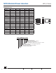
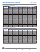
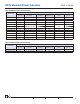
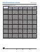
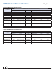
DIMENSIONS (mm)
Series A B C max. D typ. E typ.
NPIS310E 3.0 ± 0.2 3.0 ± 0.2 1.0 0.9 1.2
NPIS312E 3.0 ± 0.2 3.0 ± 0.2 1.2 0.9 1.2
NPIS315E 3.0 ± 0.2 3.0 ± 0.2 1.5 0.9 1.2
NPIS320E 3.0 ± 0.2 3.0 ± 0.2 2.0 0.9 1.2
NPIS410E 4.0 ± 0.2 4.0 ± 0.2 1.0 1.1 1.8
NPIS412E 4.0 ± 0.2 4.0 ± 0.2 1.2 1.1 1.8
NPIS415E 4.0 ± 0.2 4.0 ± 0.2 1.5 1.1 1.8
NPIS418E 4.0 ± 0.2 4.0 ± 0.2 1.8 1.1 1.8
NPIS420E 4.0 ± 0.2 4.0 ± 0.2 2.0 1.1 1.8
NPIS425E 4.0 ± 0.2 4.0 ± 0.2 2.5 1.1 1.8
NPIS430E 4.0 ± 0.2 4.0 ± 0.2 3.0 1.1 1.8
NPIS510E 5.0 ± 0.2 5.0 ± 0.2 1.0 1.75 1.5
NPIS520E 5.0 ± 0.2 5.0 ± 0.2 2.0 1.75 1.5
NPIS525E 5.0 ± 0.2 5.0 ± 0.2 2.5 1.75 1.5
NPIS530E 5.0 ± 0.2 5.0 ± 0.2 3.0 1.75 1.5
NPIS612E 6.0 ± 0.2 6.0 ± 0.2 1.2 2.0 2.0
NPIS615E 6.0 ± 0.2 6.0 ± 0.2 1.5 2.0 2.0
NPIS620E 6.0 ± 0.2 6.0 ± 0.2 2.0 2.0 2.0
NPIS625E 6.0 ± 0.2 6.0 ± 0.2 2.5 2.0 2.0
NPIS_E Series
NPIS Shielded Power Inductors
C
A
B
220
D
E
D
NPIS
42 E
150
M
TR
F
Termination Finish:
F = Standard Pb-free (100%Sn)
Packaging: TR = Tape & Reel
Inductance Tolerance Code: K=±10%, M=±20%, Y=±30%
Inductance Code (μH): 1st two digits are signifi cant,
3rd digit is multiplier.
Construction Code (see drawing for details)
Size Code (see table for details)
Series
PART NUMBER SYSTEM