
Datasheet


1
NIC COMPONENTS CORP. www.niccomp.com www.lowESR.com www.RFpassives.com www.SMTmagnetics.com
®
Specications are subject to change
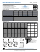
NPIS__LS Series
FEATURES
• SHIELDED POWER INDUCTOR
• HIGH CURRENT (UP TO 13.8 AMPS)
• SURFACE MOUNTABLE CONSTRUCTION
• HIGH INDUCTANCE (UP TO 330µH)
• TAPED AND REELED FOR AUTOMATIC INSERTION
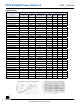
Case Size NPIS20LS NPIS21LS NPIS31LS NPIS32LS NPIS35LS
Inductance Range 0.47 ~ 10μH 0.47 ~ 22μH 1.0 ~ 62μH 0.82 ~ 100μH 1.0 ~ 68μH
Case Size NPIS41LS NPIS48LS NPIS42LS NPIS43LS NPIS52LS
Inductance Range 0.82 ~ 100μH 1.0 ~ 220μH 1.0 ~ 100μH 0.91 ~ 120μH 0.47 ~ 100μH
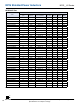
Case Size NPIS54LS NPIS62LS NPIS63LS NPIS65LS NPIS84LS
Inductance Range 1.0 ~ 100μH 0.5 ~ 22μH 1.5 ~ 100μH 0.82 ~ 330μH 0.82 ~ 330μH
Ambient Operating Temperature Range -40°C ~ +125°C (including self-heating)*
Temperatrue Rise at Irms Maximum +40°C Temperature Rise
Inductance Change at Isat Maximum -30% Inductance Drop From Initial Measured Value
Inductance Tolerance ±20% (M), ±30% (Y)
Resistance to Solder Heat +260°C for 10 seconds
CHARACTERISTICS
NPIS Shielded Power Inductors
*See Part Number System for Details
RoHS
Compliant
includes all homogeneous materials
DIMENSIONS (mm)
Series A B C d e f G I H
NPIS20LS 2.5 ± 0.1 2.0 ± 0.1 1.0 Max. 1.5 ± 0.2 0.80 ± 0.2 0.80 ± 0.2
0.8 0.85 2
NPIS21LS 2.5 ± 0.1 2.0 ± 0.1 1.2 Max. 1.5 ± 0.2 0.80 ± 0.2 0.80 ± 0.2
NPIS31LS 3.0 ± 0.2 3.0 ± 0.2 1.0 Max. 2.5 ± 0.2 0.75 ± 0.2 1.5 ± 0.2
1.5 0.8 2.7NPIS32LS 3.0 ± 0.2 3.0 ± 0.2 1.2 Max. 2.5 ± 0.2 0.75 ± 0.2 1.5 ± 0.2
NPIS35LS 3.0 ± 0.2 3.0 ± 0.2 1.5 Max. 2.5 ± 0.2 0.75 ± 0.2 1.5 ± 0.2
NPIS41LS 4.0 ± 0.2 4.0 ± 0.2 1.2 Max. 3.3 ± 0.2 0.95 ± 0.2 2.1 ± 0.2
1.9 1.1 3.4
NPIS48LS 4.0 ± 0.2 4.0 ± 0.2 1.8 Max. 3.3 ± 0.2 0.95 ± 0.2 2.1 ± 0.2
NPIS42LS 4.0 ± 0.2 4.0 ± 0.2 2.0 Max. 3.3 ± 0.2 0.95 ± 0.2 2.1 ± 0.2
NPIS43LS 4.0 ± 0.2 4.0 ± 0.2 3.0 Max. 3.3 ± 0.2 0.95 ± 0.2 2.1 ± 0.2
NPIS52LS 5.0 ± 0.2 5.0 ± 0.2 2.0 Max. 4.0 ± 0.2 1.25 ± 0.2 2.5 ± 0.2
2.3 1.4 4.2
NPIS54LS 5.0 ± 0.2 5.0 ± 0.2 4.0 Max. 4.0 ± 0.2 1.25 ± 0.2 2.5 ± 0.2
NPIS62LS 6.0 ± 0.3 6.0 ± 0.3 2.0 Max. 4.9 ± 0.3 1.55 ± 0.3 2.9 ± 0.3
2.8 1.7 5.7NPIS63LS 6.0 ± 0.3 6.0 ± 0.3 2.8 Max. 4.9 ± 0.3 1.55 ± 0.3 2.9 ± 0.3
NPIS65LS 6.0 ± 0.3 6.0 ± 0.3 4.5 Max. 4.9 ± 0.3 1.55 ± 0.3 2.9 ± 0.3
NPIS84LS 8.0 ± 0.3 8.0 ± 0.3 4.2 Max. 6.3 ± 0.3 2.00 ± 0.3 4.0 ± 0.3 3.8 2.2 7.5
NPIS2*LS
NPIS3*LS, NPIS4*LS
NPIS6*LS, NPIS8*LS
I
NPIS5*LS
All Sizes
C
REFLOW SOLDERING
LAND PATTERN (ALL SIZES)
AA
f
f
f
B B B
d d d
A
e
e
e
NPIS
31 LS
470
M
TR
F
RoHS Compliant
Packaging: TR = Tape & Reel
Inductance Tolerance Code: M=±20%
Inductance Code (µH): 1st two digits are
signicant, 3rd digit is multiplier.
Construction Code (see drawing for details)
Size Code (see table for details)
Series
PART NUMBER SYSTEM
H
I
G
*Specications reect recent product changes. For more information refer to PCN announcement [Link]