
Instructions / Assembly
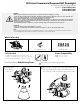

Adjust CCT or Lumen output by setting the switch positions on the back of the xture to the desired settings.
CLR Kit Installation Without Existing Frame
Make sure all power is turned o before beginning installation
Make wiring connection to junction box.
a. Connect Black wire to line wire.
b. Connect White wire to neutral wire
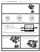
Identity xture location and cut rough-in hole. Cut a 5½” to
7” diameter hole for CLR6 and a 7½” to 9¼” diameter hole
for CLR8.
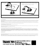
Fasten the LED
retrot kit MC
cable to a eld
installed j-box
(not supplied)
per local
electrical code
using a standard
MC connector
(not supplied).
4
1 2
J-Box
LINE
Black (line)
Ground
White (neutral)
Purple (dim +)
Grey (dim -)
Black (line)
Green (ground)
White (neutral)
Purple (dim +)
Grey (dim -)
CLR
CLR6 CLR8
5½” to 7” diameter
7½” to 9¼” diameter
c. Connect Green wire to ground wire
d. Route and connect Purple and Grey 0-10V dimming control wires in
accordance with dimmer instructions and electrical code.
NOTE: If 0-10V dimming is NOT to be connected, it is recommended to cut o the exposed, tinned leads on the purple and grey
wires, and cover the ends with a small piece of electrical tape or wire nut. If bare 0-10V control wires should accidentally
touch a grounded surface, it could cause unintended ickering or dimming of the light xture.
1000LM
1500LM
3000K
3500K
4000K
5000K
1500LM
2000LM
3000K
3500K
4000K
5000K
3
CLR82SWRVS9WH
CLR62SWRVS9WH
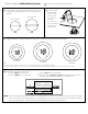
Note:
1) Power selection switch is a two-position switch that will adjust light output: low/high.
2) CCT selection switch is a four-position switch that will adjust Color Temperature between 3000K, 3500K, 4000K, or 5000K.
2000LM
3000LM
3000K
3500K
4000K
5000K
CLR82HWRVS9WH