USER’S MANUAL DP2 SERIES 24/7 SUPPORT www.NightOwlSP.
Thank you for choosing Night Owl Security Products! By purchasing a Night Owl product, you receive a one (1) year warranty covering manufacturing defects in material and workmanship. In addition to warranty and technical support benefits, you have access to our vast library of free instructional “How to Videos.” For all of our Support Videos, click www.youtube.com/nightowlsp to access Night Owl’s YouTube page.
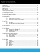
Table of Contents FCC Warning..........................................................................................................5 Safety Instructions................................................................................................. 6 Specifications........................................................................................................7 DVR Diagram.........................................................................................................
8.3 Scenario...................................................................................... 8.3.1 Pre-defined Scenarios................................................................... 8.4 Backup and Exporting Recordings.................................................. 8.4.1 Backup........................................................................................ 8.5 Storage........................................................................................ 8.6 Network....................
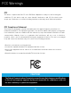
FCC Warnings FCC This device complies with Part 15 of the FCC Rules. Operation is subject to the following two conditions: (1) this device may not cause harmful interference and (2) this device must accept any interference received, including interference that may cause undesired operation. FCC Compliance Statement These limits are designed to provide reasonable protection against frequency interference in residential installation.
Safety Instructions USE THE PROVIDED POWER ADAPTER. Do not use this product with a power source that applies more than the specified voltage. NEVER INSERT METAL INTO THE DVR CASE OR ITS OPENINGS. Inserting metal into the DVR case may cause electric shock. DO NOT OPERATE IN WET OR DUSTY AREAS. Avoid placing the DVR in areas such as a damp basement or dusty attic. DO NOT EXPOSE THE DVR TO RAIN OR USE NEAR WATER. If the DVR accidentally gets wet, unplug it and contact technical support immediately.
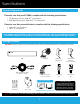
Specifications System Requirements Please be sure that your PC/MAC® complies with the following specifications: • PC Operating System: Windows® 10 and above • MAC Operating System: MAC OS X® 10.9 and above Please be sure that your mobile device complies with the following specifications: • • Android™: 8.0 and above iOS®: 12.4 and above THIS MANUAL WAS ACCURATE AT THE TIME IT WAS COMPLETED. DUE TO OUR ONGOING EFFORT TO CONSTANTLY IMPROVE OUR PRODUCTS, SPECIFICATIONS MAY HAVE BEEN ADDED OR CHANGED. 4.
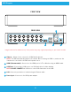
DVR Diagram FRONT VIEW REAR VIEW 1 4 2 3 5 Images used are for reference only. Your product may vary slightly depending on your model number. 1 Video In – Allows for the connection of BNC wired cameras. NOTE: The DVR automatically detects the camera. Before turning the DVR on, make sure the cameras are connected to the DVR and a power source. 2 HDMI (Recommended) – Connects to the HDMI port of a TV or Monitor using an HDMI cable.
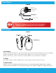
Camera Diagram CAMERA 2MP Resolution Wide Viewing Angle 90º Night Vision up to 100 ft. Built-In Spotlight 3-Axis Mounting Bracket (Vandal-Proof Wire Camera Protection) Video/Power Cables Connect all cameras locally before final placement to ensure that all components function properly. Mouse Diagram MOUSE Live Viewing: Double-click the left button on any camera view in split-screen mode to bring it to full screen display. Double-click again to return to split-screen mode.
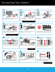
Connecting Your System 1 2 HDMI HDMI Plug one end of the included HDMI cable into the HDMI port on the back of the DVR. 3 USB Plug the other end of the HDMI cable into the back of your TV or Monitor. Plug the USB mouse into the USB port on the back of the DVR. NOTE: To view cameras, TV or Monitor must be tuned to the same input the HDMI is plugged into. 4 5 ROUTER (NOT INCLUDED) ETHERNET ETHERNET Plug one end of the included Ethernet cable into the LAN port on the back of the DVR.
Downloading Night Owl Protect 1 If you’re a First Time User, download Night Owl Protect from the App Store or Google Play Store onto your Smart Device. If you already have an account skip to Chapter 3 Step B. 2 Create and verify your Night Owl Protect account. Use the Night Owl Protect login credentials to log into the DVR in Chapter 3 Step B. NOTE: Setup is the same for Smartphone and Tablet.
Startup Wizard Connected DVRs automatically search for the latest firmware version. If you are NOT going to connect your DVR to the Internet, follow the onscreen prompts for updating the firmware and registering the device. Skip to “Don’t Want to Connect the DVR to the Internet.” 3.1 Connected to the Internet A If you have NOT created a Night Owl Protect account, click “First Time Users” and follow the onscreen steps.
3.2 Don’t Want to Connect the DVR to the Internet Night Owl Strongly Recommends connecting the DVR to the Internet. If you have decided not to connect: • You must manually update the device’s firmware to the latest version to receive Technical Phone Support. The latest firmware version is available on the device’s support page on the Night Owl Support Site. • The DVR must be registered to receive Technical Phone Support. • You cannot view your system remotely.
Live View 4.1 Live View The Live View screen is where you view your cameras and gain access to the Tool Bar and Menu. When you log into the system, the display is in full screen mode. Right click the mouse to display the Tool Bar (bottom of screen) and Function Panel (right side of screen). Left click on the Full Screen icon to close the Tool Bar and Function Panel.
4.
Video Playback The Playback Panel allows you to view recorded events. Right click on the Live View to access the Tool Bar. Left click on the Tool Bar to access the Playback Panel. Full Screen CH Layout Playback Event Seach / Control Bar Backup Timeline: Slide to Search Return to Live View Step 1: From the CHANNEL list, select the channel(s) you want to search for recordings.
Video Backup Backup your recordings on a USB Flash Drive or External HDD. Before inserting a USB Flash Drive or connecting an External HDD to the DVR, it must be formatted to FAT32/ExFat WARNING: Formatting erases ALL data on the USB or HDD NOTE: DO NOT connect the DVR’s hard disk drive to your PC or Mac! 6.1 Formatting a USB Flash Drive and External HDD 6.1.1 Formatting for Windows OS 1 2 3 4 Insert an empty Flash Drive or connect to an external HDD into a USB port on your PC.
5 6 7 Locate “Format” on the dropdown list and click it. The Format Menu opens. In the “File System” field select FAT32 and click “Start.” Don’t unplug the Flash Drive or external HDD until formatting is complete. 6.1.2 Formatting for Mac OS 1 2 Plug the USB Flash Drive or connect the extenal HDD into your Mac. Go to Applications>Utilities and launch Disk Utility.
3 Click the USB Flash Drive or external HDD in the sidebar in Disk Utility. 4 Click “Erase” in the Disk Utility Toolbar. 5 6 Create a name and click on the Format dropdown menu and choose either MS-DOS (FAT32) or ExFAT. Click “Erase.
6.2 Video Bakup Right click on the Live View screen to bring up the Tool Bar. Left click to access the playback panel. Left click to open the Backup Menu. Follow the steps below to backup video. VIDEO / LOG SOURCE DESTINATION TARGET / USB DEVICE CALENDAR USB PATH CHANNEL BACKUP NOTE: You can play the videos that you backup in the default media players for macOS and Windows. Step1: Under SOURCE, choose the data type (VIDEO or LOG). Use the CALENDAR to select the time range and date you want to copy.
DVR and Channel Status 7.1 Status & Operation The icons below keep you up to date on the DVR and its Channel’s statuses. 7.1.
Main Menu 8.1 Camera Left click “Camera” on the Main Menu to access submenus to adjust camera settings. 8.1.
8.1.2 Device 1 2 3 4 5 6 1 CHANNEL TITLE - Click to name the channel (up to 63 characters). The default name is the channel number. 2 ENABLE - You can enable or disable the Time Stamp. When turned on, the recording time displays on the channel’s Live View. 3 CACHE TIME (MSEC) - Cache time determines the buffering time for playbacks. 4 CAMERA TYPE - The camera type is detected automatically.
8.1.4 Detection Access each cameras detection settings. 8.2 Record 1 2 3 4 5 6 Set the parameters for Live View, Record Streaming, and Sub Streaming. 1 IMAGE SIZE: Select the image size for each channel. Note: The options available for IMAGE SIZE depend on the connected camera. 2 3 QUALITY: Select the video quality for each channel. The higher the value, the better the image quality. I.P.S.: Image per Second, the higher the value, the smoother the video.
8.3 Scenario Adjust the Recording Mode, Push Notifications, Light Triggered, Recording Area, and Recording Sensitivity Settings. 1 2 3 4 5 6 7 8 9 8.3.1 Pre-defined Scenarios The pre-defined scenarios are created for you to quickly enable the recording and notification functions which are used frequently. Click to select or change recording modes. 1 TIME LAPSE - Default setting for all channels. The DVR records 24/7 at 1 FPS (Frame Per Second). If an event is detected, the DVR records at full FPS.
By default, the DVR is set to record the full screen (No red grid) Set to record full screen (default value) 9 Set to not record any event Only right section of the screen will record RECORDING SENSITIVITY - Adjust the motion sensitivity needed to trigger a recording (Higher sensitivity = more recordings). 8.4 Backup and Exporting Recordings 8.4.1 Backup Note: Before inserting a USB flash drive into the DVR, it must be formatted to FAT32.
The screen below lets you choose the parameters for the video backup. Follow the steps below to backup videos. VIDEO / LOG SOURCE DESTINATION TARGET / USB DEVICE CALENDAR USB PATH CHANNEL BACKUP Step 1: Under SOURCE, choose the data type (VIDEO or LOG). Use the CALENDAR to select the time range and date you want to copy. Dates with video recordings are highlighted in blue. Step 2: Select the CHANNEL(s) to copy.
8.5 Storage 3 4 5 1 2 1 OVERWRITE - By default, HDD Overwrite is set to ON. When on, the 2 KEEP DATA LIMITS (DAYS) - Select how many days to save the recording data, from 1 to 31 days. Once the assigned amount of days is reached, the recorded data is removed. Select OFF to disable this function. 3 icon appears on the screen. HDD details - Check the details of the selected hard disk drive. 4 HDD Format - Click to format the selected hard disk drive and erase all data.
8.6 Network WAN is used to connect the DVR to the Internet for remote access. 1 2 3 4 5 6 7 1 Network Type: DHCP Network configuration mode that gathers the network values automatically from the DHCP server. If unchecked, this value can be set manually. 2 IP: Network address of the connected DVR. 3 Gateway: The connection between two networks. This should always be the IP address of the connected router. 4 Netmask: The range of IP addresses that can be found in the network.
8.7 Remote Connection Allows you to add your DVR to the Night Owl Protect App when the DVR is connected to the Internet. 1 2 1234567890 DN1234567890 3 4 1 Login: Allows the user to login with their Night Owl Protect credentials. The user will have to enter local Admin password first to confirm ownership. If the user is already logged into the DVR with their Night Owl Protect account, the DVR will display the user’s username instead of the Login button.
8.8 Time 8.8.1 Time Setup 1 2 3 4 5 6 7 1 2 3 4 5 6 7 DATE - Set the current date. The default display format is MONTH/DATE/YEAR (M/D/Y). TIME - Set the current time in HOUR : MIN : SEC. FORMAT - Set the time display format: Y/M/D, M/D/Y or D/M/Y. NTP SERVER - Click to change the default NTP server to another server you are familiar with or keep the default NTP server. SYNC PERIOD - Select to synchronize the device’s time every day (DAILY), or turn this function off (OFF). GMT - Select your Time Zone.
8.9 Display 1 2 3 4 5 6 7 8 1 CHANNEL TITLE - Select to display the channel title on the Live View. 2 EVENT STATUS - Select to display the Event Icons on the Live View. 3 AUTO KEY LOCK(S) - Set the display’s time-out, after which the Key Lock is activated. (NEVER / 30 sec / 60 sec / 120 sec) 4 HDD DISPLAY MODE - Select REMAINING SIZE to show the remaining HDD capacity for recording, or REMAINING TIME to show the remaining recording time. 5 DISPLAY OUTPUT - Select the display resolution.
8.10 Maintain 8.10.1 System 1 2 3 1 BACKUP CONFIG / RESTORE CONFIG (a) To save the DVR’s current configurations for later use, insert a compatible USB flash drive into the USB port. Click SUBMIT in the BACKUP CONFIG field to copy the current DVR configurations to a file “System. bin” and save to your USB flash drive. (b) To restore the DVR configurations, insert the USB flash drive with the file “System.bin” into the USB port and select SUBMIT in RESTORE CONFIG field.
8.10.2 Upgrade In this menu, you can choose to upgrade your DVR (LOCAL) or the connected cameras (CAMERA). LOCAL TAB 1 2 3 4 5 1 Current Version: Display current DVR firmware version 2 Online Version: Display latest DVR firmware version in the OTA Server if there is a new version available. Click Refresh to check OTA version. 3 Release Note: New OTA version release notes if there is a new one.
CAMERA TAB 1 Save the upgrade files obtained from your installer or distributor in a compatible USB flash drive and insert it into the USB port. 2 to browse to where the firmware file is saved and choose the file to upgrade. Then, choose Choose SELECT to confirm and return to the upgrade page. 3 Repeat Step2 as many as needed until all cameras which need firmware upgrade are selected. If one firmware file applies to several IP cameras, select COPY TO to apply the same file to the applicable cameras.
8.10.3 Event Log You can see all event information (Type, Time Stamp, and Channel), or clear all Log Records.
8.10.4 Online 2 3 4 1 ANONYMOUS VIEWER LOGIN (DISABLED FEATURE) - Switch to ON to allow anonymous login. You don’t need to enter a username and password for remote access. NOTE: Although the DVR currently includes this feature, it is NOT supported by Night Owl Protect to ensure your privacy and security. 2 DROP ALL VIDEO CONNECTION - Click SUBMIT to force disconnection of all remote login credentials. 3 LOGIN FAILURE TIMES - The DVR locks the IP address after several login attempts.
8.11 Power Control Click to show the power functions. Options include Halt, Reboot, or System Logout. Icon Meaning System Halt Description Click to stop the system and remove the power adapter. Safest way to shut down. System Reboot Click to reboot the system. System Logout Click to logout and/or log in with another account. To manually logout of your DVR, follow the steps below: Click on MENU -> POWER CONTROL. Click to logout or click on icon.
APPENDIX A Right click MENU on the bottom left corner of the Tool Bar to display the main menu and submenu lists: CONNECTION DEVICE BRIGHTNESS CAMERA CONTRAST IMAGE SATURATION HUE DETECTION IMAGE SIZE RECORD QUALITY FPS (Frames Per Second) RECORDING BY PUSH SCENARIO LIGHT RECORDING AREA RECORDING SENSITIVITY EXPORT BACKUP OVERWRITE STORAGE KEEP DATA LIMIT(DAYS) WAN NETWORK REMOTE CONNECTION DATE TIME TIME FORMAT NTP SERVER TIME SETUP SYNC PERIOD GMT CLIENT TIME SYNC VIA RECORDER SYNC NTP S
CHANNEL TITLE EVENT STATUS AUTO KEY LOCK(S) HDD DISPLAY MODE DISPLAY OUTPUT DISPLAY LANGUAGE SPOT MONITOR* CALL SCREEN DURATION QUAD SCREEN DURATION BACKUP CONFIG RESTORE CONFIG RESET DEFAULT SYSTEM DEVICE TITLE ENABLE AUTO PLUG AND PLAY BIND MAC ADDRESS RESET ALL GUARD CONNECTION BAUD RATE MAINTAIN HOST ID LOCAL UPGRADE CAMERA EVENT LOG SYSTEM BACKUP ANONYMOUS VIEWER LOGIN DROP ALL CONNECTION ONLINE LOGIN FAILURE TIMES LOCK TIME FOR LOGIN FAILURES AUTO REBOOT POWER CONTROL HALT THE SYSTEM REB
APPENDIX B: Advanced Config STOP: Please do not adjust the Advanced Configuration Settings unless you are familiar with and understand the changes you are making. PRIVACY MASK You can cover certain areas on the camera image with privacy masks. Up to 4 areas could be added. PRIVACY MASK MOSAIC SIZE NAME FUNCTION MOSAIC COLOR MASK1 MASK2 OFF ON OFF ON ON ON MOSAIC COLOR TRANSPARENCY 0% 25% EDIT Select one of the 4 mask profiles available and click on EDIT to modify setting.
Glossary DP2: 1080p (2MP) HD Hi-Definition Analog System with Human Detection Technology and Built-in Motion-Activated Spotlights. DDNS: Dynamic Domain Naming System. Method for automatically updating hostnames, addresses, URL’s or other information on a given name server. DHCP: Dynamic Host Configuration Protocol. A network protocol that allows a server to automatically assign a device and IP address.
Warranty NIGHT OWL, LLC (“Night Owl”) provides the following warranty to the original retail purchaser only (the “Purchaser”) with respect to this product (the “Product”): For a period of one (1) year after the date of sale, the Product shall be free from manufacturing defects in material and workmanship. Product registration may be required to submit a warranty claim.
Disclaimer Certain uses, publication and/or distribution of video/audio recordings from security cameras and/or audio devices are prohibited or restricted by federal, state and local laws. When enabling and/or using audio recording features with your hidden security camera, be sure to comply with the laws in your country, state and locality. Mac and Mac OS X are registered trademarks of Apple Inc.
Troubleshooting If a problem occurs, you may be able to easily correct it yourself. The following table describes some common issues and their most likely solutions. Please refer to the table before calling technical support. Error Solutions 1. Confirm that all cables are connected correctly. Cable from power adapter is 2. Confirm that the power loose or is unplugged. adapter is securely connected to the back of the unit. 1. Confirm that the system is powered ON (LED indicators on the front should be ON).
Error There is no picture on selected channels/camera picture is not being displayed. Possible Causes Camera cables are loose or have become disconnected. The system beeps at startup. Solutions 1. Check the camera video cable and connections. 2. Disconnect and reconnect the cable at the system and at the camera. 3. Try moving the camera to another channel or use another cable. The beep at startup is normal.
User Information Be sure to write down all the important information below and place it in a secure location.
NEED HELP? Why Call? Our Support Site Has it All! For system manuals, troubleshooting guides, FAQs, video tutorials and more: 1 2 3 Please visit Support.NightOwlSP.com Enter the Series listed on the Product Support Sticker into the Search bar. Access the support material needed. www.NightOwlSP.com Rev 200811 iPhone, iPad, Mac and Mac OS X are registered trademarks of Apple Inc.