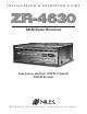
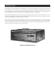
INSTALLATION & OPERATION GUIDE ZR-4630 MultiZone Receiver Four-Source, Six-Zone, 30W Per Channel AM/FM Receiver B L E N D I N G T E C H N O L O G Y A N D A R C H I T E C T U R E™
Congratulations! Thank you for purchasing the Niles ZR-4630 MultiZone Receiver, one of the most flexible and convenient audio components ever offered. The ZR-4630, like all Niles products, is built to the highest standards of quality and reliability. With proper installation and operation, you'll enjoy years of trouble-free use. Niles manufactures the industry's most complete line of custom installation components and accessories for audio/video systems.
TABLE OF CONTENTS SOURCE POWER SYNCHRONIZATION . . . . . . . . . . . . . . . . . . . . . . . . . . . . . . . . . . . . . . . . . . . . . . . . . . . . . . . . .28 CHOOSING A SYNCHRONIZATION METHOD . . . . . . . . . . . . . . . . . . . . . . . . . . . . . . . . . . . . . . . . . . . . . . . .29 Video Sync . . . . . . . . . . . . . . . . . . . . . . . . . . . . . . . . . . . . . . . . . . . . . . . . . . . . . . . . . . . . . . . . . . . . . . . . . .29 Voltage Sync . . . . . . . . . . . . . . . . . . . . . .
TABLE OF CONTENTS OPERATION FROM THE HOME THEATER ZONE . . . . . . . . . . . . . . . . . . . . . . . . . . . . . . . . . . . . . . . . . . . . . . .42 1. Integrated Home Theater using 12V Home Theater Sync and IR Repeating . . . . . . . . . . . . . . . . . . . . . .41 2. Integrated Home Theater using 12V Home Theater Sync and Niles R-4 Commands . . . . . . . . . . . . . . .42 3. Integrated Home Theater without Home Theater Sync and using Niles R-4 Commands . . . . . . . . . . . . .
TABLE OF CONTENTS Programming Documentation . . . . . . . . . . . . . . . . . . . . . . . . . . . . . . . . . . . . . . . . . . . . . . . . . . . . . . . . . . . . . . .51 ZR-4630 Programming Worksheet . . . . . . . . . . . . . . . . . . . . . . . . . . . . . . . . . . . . . . . . . . . . . . . . . . . . . . . . . .52 ZR-4630 Source-Component Programming Worksheet . . . . . . . . . . . . . . . . . . . . . . . . . . . . . . . . . . . . . . . . . . . .53 Function Keys/Buttons Programming . . . . . . . . . .
INTRODUCTION Niles Audio has recognized the need for a simple to use, cost-effective multi-zone system that can provide years of listening pleasure to music-lovers. Our engineering and product development departments have joined forces to produce an innovative multi-zone receiver that incorporates six separate zones of amplifier power, a built-in AM/FM tuner, and connections for three additional audio-source components.
FEATURES AND BENEFITS Multi-zone/Multi-source The ZR-4630 MultiZone Receiver incorporates matrix preamplifier technology to provide as many as three source components and the built-in tuner to six listening zones simultaneously. Finally, Dad can relax to the sound of his favorite music in the den while the kids are listening to their favorite music by the pool. 12-Channel 30W Amplifier for Six Zones of Stereo Sound The ZR-4630 MultiZone Receiver is an integrated solution for multi-zone applications.
FEATURES AND BENEFITS The R-4 Remote - The R-4 Remote provides system control via an ergonomic hand-held IR remote control. Zones that have been installed with Niles IR Sensors can take advantage of the R-4 Remote, providing system control from anywhere in the room. System-Wide Operation The ZR-4630 MultiZone Receiver incorporates system-wide control to activate all zones to a particular source component. An ALL OFF command is also included for complete system shutdown from any zone in the system.
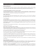
PARTS GUIDE (ZR-4630) LED Zone ON/OFF Indicator Main Power Switch Zone Label Slots Tuner Controls Removable Programming Cover Sensor for Capturing IR Commands Tuner Display Zone All On/Page Enable Switches Programming Controls and Indicators Sync Inputs Audio Inputs Keypad Inputs Paging Input Individual Zone Preamplifier Output DB-9 Computer Interface Flasher Outputs System Expansion IR Input Removable Speaker Connector 12V Control Output Fixed/Variable Preamplifier Adjustment Switch Figur
PARTS GUIDE (ZR-4630) Keypad Inputs Six female RJ-45 jacks for the connection of the IntelliPad Ci® Master Keypad Modules. LED Zone ON/OFF Indicators Provides individual ON/OFF indication for each zone. Zone Label Slots Coined slot for placing included zone labels for easy identification. System Expansion Two female RJ-45 jacks for connecting multiple receivers together in larger multi-zone systems.
PARTS GUIDE (R-4 REMOTE) INCLUDED Zone OFF Button Zone Volume Buttons Function Buttons Zone Mute Button Source Buttons Figure 2 Zone Mute Button A quick tap of this button mutes the sound in a zone. A quick tap of this button restores sound in a zone that is currently muted. Source Buttons A quick tap of any of these buttons causes the zone to turn on and a source component to be selected. Pressing and holding these buttons for longer than three seconds causes all enabled zones to turn on.
PARTS GUIDE (SOLO™ MASTER & NUMERIC™ ACCESSORY KEYPAD MODULES) SOLD SEPARATELY Master Keys Function Keys Function Keys Zone Off Key Mute Key Zone Volume Key IntelliPad Ci® Solo™ Master Keypad Module IntelliPad Ci® Numeric™ Accessory Keypad Module Figure 3 Zone Mute Key A quick tap of this key mutes the sound in a zone. A quick tap of this key restores sound in a zone that is currently muted.
SYSTEM CONFIGURATIONS CONFIGURATION 1 - SIX ZONES Source Components AC Power Cord AUDIO DIGITAL L CD CHANGER Switched AC Outlet Niles AC-3 R DVD DIGITAL AUDIO VIDEO L R Unswitched AC Outlet 12V Trigger DSS DIGITAL AUDIO VIDEO L R PHONE Niles IRC-2P MicroFlashers Audio Cables CK O ZONE 4 CK O K N CK O U ZONE 5 K AR ED SE N NO CK O U K AR ED SE NO N CK O U INFR ED SE INFR AR NO K AR ED SE NO N T U INFR ED SE N INFR AR NO T K T U T N CK O INFR ED SE
SYSTEM CONFIGURATIONS Keypads and IR Sensors Keypads and IR sensors enable the user to control the Niles ZR-4630 MultiZone Receiver and its connected source components. Source component IR commands are programmed into the Niles ZR-4630 MultiZone Receiver. These commands are then triggered when the user presses a keypad button or issues a Niles IR command to an IR sensor. Each zone on the ZR-4630 has a corresponding RJ-45 keypad connector that is used to connect one Solo™ Master Keypad Module.
SYSTEM CONFIGURATIONS CONFIGURATION 2 – ADDING ZONES USING MULTIPLE ZR-4630’S More than one ZR-4630 can be used if the system requires more than six zones. A maximum of three ZR-4630’s, providing up to 18 zones, can be combined to create a larger multi-zone/multi-source system. One ZR-4630 is designated as the Master and the others as Slaves (see Installation Settings on page 58 for more details).
SYSTEM CONFIGURATIONS CONFIGURATION 3 – DISTRIBUTING SOURCE-COMPONENT AUDIO SIGNALS When sharing source components with three ZR-4630’s (see Figure 6) or two ZR-4630’s and a Home Theater system (see Figure 7), a Niles AVDA-3 Audio/Video Distribution Amplifier is required for each source.
SYSTEM CONFIGURATIONS CONFIGURATION 3 – DISTRIBUTING SOURCE-COMPONENT AUDIO SIGNALS Niles AVDA-3 Distribution Amplifier Source Components AUDIO L DIGITAL CD CHANGER R DVD DIGITAL Niles IRC-2P MicroFlashers AUDIO VIDEO L R DSS DIGITAL AUDIO VIDEO L R PHONE Designated as the Master Four Pair Twisted Cable DIGITAL 1 2 AUDIO VIDEO L R DVD FRONT SURROUND L L R R Designated as Slave #1 DSS CD CENTER L Video 1 R Video 2 Home Theater Receiver Figure 7 If you are installing three ZR-4
SYSTEM CONFIGURATIONS CONFIGURATION 4 – INTEGRATING AN IR-CONTROLLED HOME THEATER An IR-controlled Home Theater surround-sound receiver can be integrated to share source components in a system with the ZR-4630. Audio Cables with RCA Y-Adapters Source Components AUDIO L Home Theater Receiver DIGITAL 1 2 AUDIO VIDEO L R L R R DVD DSS CD CENTER L Video 1 R Video 2 CD CHANGER REAR FRONT L DVD DIGITAL R DIGITAL Niles IRC-2P MicroFlashers AUDIO VIDEO L R 12V D.C.
SYSTEM CONFIGURATIONS CONFIGURATION 5 – INTEGRATING A HOME THEATER USING AN INTELLICONTROL A Home Theater system controlled by a Niles IntelliControl can be integrated to share source components in a system with the ZR-4630. Audio Cables with RCA Y-Adapters Source Components AUDIO L Home Theater Receiver DIGITAL 1 2 AUDIO VIDEO L R DVD FRONT L DIGITAL REAR L R R DVD DSS CD CENTER L Video 1 R Video 2 CD CHANGER R DIGITAL Niles IRC-2P MicroFlashers AUDIO VIDEO L R 12V D.C.
SYSTEM CONFIGURATIONS CONFIGURATION 6 – MULTIPLE SOLO™ MASTER KEYPAD MODULES IN A ZONE The single zone of a Niles ZR-4630 MultiZone Receiver can be expanded to contain multiple Solo™ Master Keypad Modules providing control from many locations within the zone. A Niles IntelliPad® Ci Expander™ is required to connect multiple keypads in a single zone. A maximum of five Solo™ Master Keypad Modules can be included in a single zone using two Expanders.
SYSTEM CONFIGURATIONS CONFIGURATION 7 – MULTIPLE LISTENING AREAS IN A ZONE A single zone of the ZR-4630 can be set up to contain more than one listening area (i.e., an adjacent living room and dining room). This configuration is chosen when the speakers in the zone are not required to be played at separate volume levels or to be on/off separately.
SYSTEM CONFIGURATIONS CONFIGURATION 8 – EXTERNAL AMPLIFIER IN A ZONE FOR MORE POWER Each zone of the ZR-4630 provides RCA preamplifier output connections for the connection of external amplifiers. External amplifiers can be used to provide more power in a zone.
SYSTEM CONFIGURATIONS CONFIGURATION 9 – EXTERNAL AMPLIFIER IN A ZONE FOR MULTIPLE LISTENING AREAS A zone of the ZR-4630 can be set-up to contain more than one listening area by adding an external amplifier (i.e., an adjacent living room and dining room area). This configuration is chosen when the speakers included in the zone are not required to be played at separate volume levels or to be ON/OFF separately.
SYSTEM CONFIGURATIONS CONFIGURATION 10 – EXTERNAL AMPLIFIER IN A ZONE FOR MULTIPLE ROOMS The preamplifier output connectors on the ZR-4630 for zones 4, 5 and 6 have a fixed/variable setting. Using the fixed setting with an external amplifier enables a zone to be divided up into individual rooms using conventional Niles Impedance Matching Volume Controls.
SYSTEM CONFIGURATIONS CONFIGURATION 11 – SYSTEM PAGING AND EXTERNAL TELEPHONE SYSTEM A Paging Input connection on the rear panel of the ZR-4630 provides a connection for the paging output signal of popular telephone systems for voice paging through the speakers in the listening zones (see Figure 15). Paging volume level can be adjusted by the ZR-4630 (see Installation Settings on page 59 for more information).
SYSTEM CONFIGURATIONS CONFIGURATION 12 – IR REPEATING FOR CONTROL OF LOCAL COMPONENTS An IR Repeating System can be integrated into a room connected to the Niles ZR-4630 (see Figure 17). This enables a single IR Sensor (installed in that room) to control local components with a hand-held IR remote control. In Figure 17, a Niles IR Sensor is connected to a Niles IRP-6+ for control of local components and to a Niles ZR4630 for control of distributed components.
COMPONENT COMPATIBILITY Infrared Command Compatibility IR control testing was conducted on many equipment brands to determine their compatibility with the ZR4630. Typical A/V source components (i.e., CD, DVD, DSS, Cable Boxes, etc.) from each brand were chosen for the test. All brands listed below passed the test.
SOURCE POWER SYNCHRONIZATION WHAT IS SOURCE-POWER SYNCHRONIZATION? The ZR-4630 has been designed to keep track of the ON/OFF condition of the three source components connected to the system. This enables source components that utilize the same IR command for ON and OFF to be automated. For this feature to function as designed, you need “synchronization (sync)” between the ZR-4630 and source components that utilize the same IR command for ON and OFF.
SOURCE POWER SYNCHRONIZATION CHOOSING A SYNCHRONIZATION METHOD Once you establish that all source components in the system have compatible IR commands, the next step is to choose the appropriate Sync Method for each component. There are two ways to detect when a component is ON or OFF: Video or Voltage Sync. TV DSS DIGITAL AUDIO VIDEO L R PHONE Video Input RCA Y-Adapter Splitting Video Output Figure 18 Video Sync Video Sync is the easiest and most reliable method of synchronization.
SOURCE POWER SYNCHRONIZATION Voltage Sync Voltage Sync is also a reliable method of synchronization if chosen and implemented correctly. The Sync Inputs can detect the control out voltage from a Niles Signal Sensing product interfaced to the source component. Obtaining Voltage Sync Current Sensing Current Sensing synchronizes a component by detecting the changes in the AC power draw that occurs with a component when it turns ON and OFF.
SOURCE POWER SYNCHRONIZATION Light Sensing Using a light sensor (LS-1) to synchronize your components is usually your last choice, simply because the other choices are more reliable. The Niles LS-1 Light Sensor can synchronize a component by sensing changes in light. The 12V output of the LS-1 is then connected to the ZR-4630’s Sync Input dedicated for that component, a miniplug to RCA adapter is required for this connection (see Connections for more information).
OPERATIONAL OVERVIEW MASTER KEYS/SOURCE BUTTONS The Master Keys available on the Solo™ Master Keypad Module and the Source Buttons on the hand-held R-4 Remote (Figure 21) provide “one-touch activation” of the ZR-4630 and source components. The Master Keys on the Solo™ Master Keypad Module are equipped with back lighting LEDs for indicating Zone ON/OFF, Zone Mute, and Zone Input Selection status.
OPERATIONAL OVERVIEW Master Key/Source Button Events When you press a Master Key on a Solo™ Master Keypad Module or a Source Button on the hand held R-4 Remote, as many as four events occur. The first event is factory programmed and activates the zone which you are located. The second event is factory programmed and selects the proper source input corresponding to the Master Key or Source Button pressed (1 = Tuner, 2 = Input 2, 3 = Input 3, 4 = Input 4).
OPERATIONAL OVERVIEW MASTER KEY/SOURCE BUTTON OPERATION The Master Key/Source Buttons have two methods for operating the system. Single-Zone Operation The first method, a quick tap of a Master Key/Source Button in a zone (holding the Key/Button for less than three seconds), causes only that zone to turn ON. The Master Key quickly tapped illuminates GREEN after the zone turns ON. A zone turns ON to its last volume setting.
OPERATIONAL OVERVIEW OFF Key Events When you press the OFF Key/Button, as many as two events occur. The first event is factory programmed and is responsible for turning the zone or all zones OFF every time the OFF Key/Button is pressed. The second event is responsible for turning OFF the source components and only occurs if the zone turning OFF was the last zone ON in the system (including the Home Theater Zone sharing source components). There is no programming required for this event.
OPERATIONAL OVERVIEW VOLUME KEYS/VOLUME BUTTONS The Volume Keys on the Solo™ Master Keypad Module and the Volume Buttons on the hand-held R-4 Remote provide control of volume for individual zones. Volume Buttons on the hand-held R-4 Remote Volume Keys on the Solo™ Master Keypad Module Figure 23 Volume Keys/Volume Buttons Operation Pressing the Volume + or the Volume - Keys/Buttons raises and lowers the speaker output and the preamplifier output for the zone in which you are located.
OPERATIONAL OVERVIEW MUTE KEY/MUTE BUTTON The Mute Key/Button provides a method of turning the sound ON/OFF for a brief moment in an individual zone without turning the zone OFF (this also prevents the source component from being turned OFF).
OPERATIONAL OVERVIEW FUNCTION KEYS/BUTTONS The Solo™ Master Keypad Module, the Numeric™ Accessory Keypad Module, and the hand-held R-4 Remote include various function keys for control of the built-in tuner and the connected source components. Figure 26 illustrates the available function keys for all of the control devices.
OPERATIONAL OVERVIEW Function Key/Button Operation for the Built-in Tuner The commands for operation of the built-in tuner from the function keys/Buttons are pre-programmed. Figure 27 depicts the available commands for the tuner, their function key/button location, and a description of their action on the tuner.
OPERATIONAL OVERVIEW FRONT PANEL TUNER OPERATION Preset Buttons Station Scan Buttons Band Shift Button Frequency Indicator Band Indicator Stereo Indicator Figure 27 Band-Shift Button The Band Shift Button toggles the selected tuning band between AM and FM. Station Scan Buttons A quick tap of the Station Scan Buttons increments the tuner one frequency step.
OPERATIONAL OVERVIEW IDENTICAL SOURCE COMPONENTS The ZR-4630 routes the individual source component IR commands with which it has been programmed to specific Flasher Outputs. This provides individual control of identical source components (i.e., two DSS receivers of the same brand and model). These programmed IR commands are routed to the individual Flasher Outputs based on the source components for which they were programmed.
OPERATIONAL OVERVIEW OPERATING A SYSTEM INTEGRATED WITH A HOME THEATER Operation from the Stereo Zones Provided by the ZR-4630 User operation from the zones provided by ZR-4630’s, are not affected when integrating a Home Theater to share source components (see System Configurations 4 & 5). Solo™ Master Keypad Modules in each zone independently operate the zone to which they are dedicated (i.e., Zone ON/OFF, Volume Up/Down, Mute).
OPERATIONAL OVERVIEW When the Home Theater turns ON, it provides a 12V Status signal that is connected to the Home Theater Sync Input on the rear panel of the ZR-4630. This 12V Status signal provides the ON/OFF status of the Home Theater to the ZR-4630. The moment a valid Home Theater Sync signal is present at the ZR-4630, the ZR-4630’s 12V Control Output sends a turn-on trigger for a Voltage-Triggered AC Power Strip (i.e., Niles AC-3), activating latching source components.
INSTALLATION PLACEMENT Place the ZR-4630 on a flat, level surface such as a table or shelf, with its weight equally distributed on each of its four feet. Placing the weight of the amplifier on the rear or front panel for even an instant will result in damage to the amplifier's connectors and controls. Like any high-fidelity component, the ZR-4630 will last much longer if it is given adequate ventilation for proper cooling.
CONNECTIONS TERMINATING FOUR-PAIR TWISTED CABLE The Solo™ Master Keypad Modules, the Expander, and the ZR-4630’s System Expansion connections require a four-pair twisted cable with a one-to-one wiring configuration. To maintain consistency throughout all Intellipad Ci installations, we recommend the color-coding pattern described in Figure 31. However, you may follow the color-coding pattern of your choice, as long as it is used consistently throughout the system.
CONNECTIONS CONNECTING IR SENSORS An IR sensor can be connected to a Solo™ Master Keypad Module in one of two ways, directly with a four-pair twisted cable (see Figures 34 and 35), or with a three-wire to RJ45 adapter available from Niles for IR Sensors installed with two-conductor shielded cable (see Figure 36 and the Accessories Section of this manual). Connecting a Sensor using Four-Pair Twisted Cable As shown in Figure 34, one end of the fourpair twisted cable connects with bare wire to the IR Sensor.
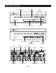
CONNECTIONS 10 11 1 2 3 4 5 6 7 8 9 12 Figure 37 13 14 15 SOURCE-COMPONENT POWER AND HOME THEATER SYNCHRONIZATION SIGNALS 16 17 2.
CONNECTIONS SYSTEM EXPANSION 11 1. 5 System Expansion Input to System Expansion Output 5. Four-pair twisted cable, terminated with male RJ-45 plugs, connects multiple ZR-4630's using the System Expansion Input and Output terminals. Connections are made from the Input of one of the ZR-4630's to the Output of another, and so on (for more information on Terminating Four-Pair Twisted Cable, refer to page 44). SOURCE-COMPONENT AUDIO SIGNALS 12 1. IR FLASHERS 6 Low-Output Flasher to the Flasher Outputs 6.
CONNECTIONS CONNECTING AN IR SENSOR FOR LOCAL SYSTEM CONTROL IR Sensors installed in zones for hand-held IR remote control of the ZR-4630 and its source components can also be used to control local components (i.e., a TV, DSS, DVD, and a surround-sound system located in the master bedroom zone as shown in figure 38). The IR Sensor connects normally to the Solo™ Master Keypad to control the ZR-4630 and its connected source components.
CONNECTIONS CONNECTING AN A/B AMPLIFIER SWITCH FOR LOCAL SYSTEM SELECTION A Niles SPK-1 Voltage Activated Speaker Level A/B Switcher connects to both the ZR-4630 and a local system to provide sound from each system to the same speakers located in a single zone. The local system only connects to the speakers when the local system is turned on. The Niles ZR-4630 connects to the speakers by default when the local system is off.
PROGRAMMING OVERVIEW INSTALLER PROGRAMMING PANEL IR commands needed for control of connected external source-components are programmed into the ZR-4630’s program memory using the hidden programming controls on the front panel (see figure 42).
PROGRAMMING OVERVIEW ZR-4630 Programming Worksheet A completed Tuner and Zone Label Programming Worksheet is required for each ZR-4630 installed in a system. The programming information that should be included is detailed in figure 43. 1 2 JOB TITLE SYSTEM DESIGNER Mr. Smith Joe Installer Document the customer’s name. Document the system designer’s name.
PROGRAMMING OVERVIEW ZR-4630 Source-Component Programming Worksheet A completed source-component Programming Worksheet is required for each source-component included in the system. The programming information that should be included is detailed in figures 44, 45, and 46. 1 3 2 JOB TITLE SYSTEM DESIGNER Mr. Smith Joe Installer Document the customer’s name. Document the system designer’s name.
PROGRAMMING OVERVIEW Function Keys/Buttons Programming Figure 45 depicts the section of the Programming Worksheet that corresponds to the source-component function key/button programming. Each programmed source component has one worksheet filled out specifying what particular IR commands have been programmed and to which function key/button they have been assigned.
PROGRAMMING OVERVIEW PROGRAMMING A LEARNING REMOTE FOR ZONE OPERATION Learning remote controls can be taught the IR commands of the Niles R-4 Remote to provide individual zone operation. These IR commands operate the ZR-4630 and its associated source components from any zone equipped with an IR Sensor. Important Note: IR Sensors cannot operate a zone when used alone. They must be installed and connected to a Solo™ Master Keypad Module.
PROGRAMMING OVERVIEW teach the Niles R-4 Remote Control IR commands to the Home Theater learning remote, rather than the IR commands from the remote controls included with the shared source components.
PROGRAMMING OVERVIEW Method #3 – Controlling Shared Source Components with Niles R-4 Commands and without 12V Home Theater Status A third method of programming is available in situations where a 12V DC status signal is not available from the Home Theater. With this method, you must teach some of the Niles R-4 Remote Control IR commands to the Home Theater learning remote.
PROGRAMMING WORKSHEET 1 JOB TITLE 2 3 UNIT MODE AND ZONE LABELS (CHOOSE ONLY ONE: SYSTEM DESIGNER A, B OR C) ❏ (A) MASTER 1 2 3 4 5 6 7 8 9 10 11 12 13 14 15 16 17 18 ❏ (B) SLAVE 1 ❏ (C) SLAVE 2 4 TUNER PRESETS AM 5 1 _______________ 6 _______________ 1 _______________ 6 _______________ 2 _______________ 7 _______________ 2 _______________ 7 _______________ 3 _______________ 8 _______________ 3 _______________ 8 _______________ 4 _______________ 9 _______________
PROGRAMMING WORKSHEET 1 JOB TITLE 2 3 UNIT MODE AND ZONE LABELS (CHOOSE ONLY ONE: SYSTEM DESIGNER A, B OR C) ❏ (A) MASTER 1 2 3 4 5 6 7 8 9 10 11 12 13 14 15 16 17 18 ❏ (B) SLAVE 1 ❏ (C) SLAVE 2 4 TUNER PRESETS AM 5 1 _______________ 6 _______________ 1 _______________ 6 _______________ 2 _______________ 7 _______________ 2 _______________ 7 _______________ 3 _______________ 8 _______________ 3 _______________ 8 _______________ 4 _______________ 9 _______________
PROGRAMMING WORKSHEET 1 JOB TITLE 2 3 UNIT MODE AND ZONE LABELS (CHOOSE ONLY ONE: SYSTEM DESIGNER A, B OR C) ❏ (A) MASTER 1 2 3 4 5 6 7 8 9 10 11 12 13 14 15 16 17 18 ❏ (B) SLAVE 1 ❏ (C) SLAVE 2 4 TUNER PRESETS AM 5 1 _______________ 6 _______________ 1 _______________ 6 _______________ 2 _______________ 7 _______________ 2 _______________ 7 _______________ 3 _______________ 8 _______________ 3 _______________ 8 _______________ 4 _______________ 9 _______________
PROGRAMMING WORKSHEET 1 JOB TITLE 2 3 UNIT MODE AND ZONE LABELS (CHOOSE ONLY ONE: SYSTEM DESIGNER A, B OR C) ❏ (A) MASTER 1 2 3 4 5 6 7 8 9 10 11 12 13 14 15 16 17 18 ❏ (B) SLAVE 1 ❏ (C) SLAVE 2 4 TUNER PRESETS AM 5 1 _______________ 6 _______________ 1 _______________ 6 _______________ 2 _______________ 7 _______________ 2 _______________ 7 _______________ 3 _______________ 8 _______________ 3 _______________ 8 _______________ 4 _______________ 9 _______________
SOURCE COMPONENT PROGRAMMING WORKSHEET 1 JOB TITLE 2 3 CHOOSE MASTER KEY MASTER KEY NUMBER (2, 3, 4): ___________ 4 SYSTEM DESIGNER MASTER KEY LABEL: ____________________ PROGRAM SOURCE COMPONENT POWER COMPONENT BRAND: __________________________________ COMPONENT SYNC ❏ Yes 5 ❏ No POWER PROGRAMMING If Yes, SYNC TYPE: ❏ Video ❏ 12V ❏ Single “Power” IR Command ❏ Two Separate ON and OFF IR Commands ❏ Latching Power PROGRAM FUNCTION KEY IR COMMANDS FUNCTION KEY/BUTTON Play Stop Pause Rewind <<
SOURCE COMPONENT PROGRAMMING WORKSHEET 1 JOB TITLE 2 3 CHOOSE MASTER KEY MASTER KEY NUMBER (2, 3, 4): ___________ 4 SYSTEM DESIGNER MASTER KEY LABEL: ____________________ PROGRAM SOURCE COMPONENT POWER COMPONENT BRAND: __________________________________ COMPONENT SYNC ❏ Yes 5 ❏ No POWER PROGRAMMING If Yes, SYNC TYPE: ❏ Video ❏ 12V ❏ Single “Power” IR Command ❏ Two Separate ON and OFF IR Commands ❏ Latching Power PROGRAM FUNCTION KEY IR COMMANDS FUNCTION KEY/BUTTON Play Stop Pause Rewind <<
SOURCE COMPONENT PROGRAMMING WORKSHEET 1 JOB TITLE 2 3 CHOOSE MASTER KEY MASTER KEY NUMBER (2, 3, 4): ___________ 4 SYSTEM DESIGNER MASTER KEY LABEL: ____________________ PROGRAM SOURCE COMPONENT POWER COMPONENT BRAND: __________________________________ COMPONENT SYNC ❏ Yes 5 ❏ No POWER PROGRAMMING If Yes, SYNC TYPE: ❏ Video ❏ 12V ❏ Single “Power” IR Command ❏ Two Separate ON and OFF IR Commands ❏ Latching Power PROGRAM FUNCTION KEY IR COMMANDS FUNCTION KEY/BUTTON Play Stop Pause Rewind <<
SOURCE COMPONENT PROGRAMMING WORKSHEET 1 JOB TITLE 2 3 CHOOSE MASTER KEY MASTER KEY NUMBER (2, 3, 4): ___________ 4 SYSTEM DESIGNER MASTER KEY LABEL: ____________________ PROGRAM SOURCE COMPONENT POWER COMPONENT BRAND: __________________________________ COMPONENT SYNC ❏ Yes 5 ❏ No POWER PROGRAMMING If Yes, SYNC TYPE: ❏ Video ❏ 12V ❏ Single “Power” IR Command ❏ Two Separate ON and OFF IR Commands ❏ Latching Power PROGRAM FUNCTION KEY IR COMMANDS FUNCTION KEY/BUTTON Play Stop Pause Rewind <<
INSTALLATION SETTINGS ALL ON/PAGE DIP SWITCH SETTINGS There are six All ON/PAGE switches located on the hidden programming panel of the ZR-4630. Each of the ZR-4630's zones has a corresponding numbered switch (see Figure 40). The switches enable (Up) or disable (Down) the individual zones from responding to ALL ON commands and incoming audio pages.
INSTALLATION SETTINGS VOLUME SETTINGS The ZR-4630 has three useful volume features with customizable settings. The following is a list of the three volume features along with their default values and a description of their purpose. Maximum Turn ON and Source Change Volume Level Maximum Turn ON and Source Change Volume prevents a zone from playing too loudly when it is first turned on or if the zone changes the currently selected source.
SYSTEM PROGRAMMING STEPS PROGRAMMING THE SOURCE COMPONENTS Step 1 - Press and hold the PROGRAM button for two seconds. Three LEDs illuminate: ENTER IR, PROGRAM, and SOURCE 2. The POWER OR DISCRETE “ON” LED blinks. Step 2 - If Source Two is turned ON/OFF with IR commands, go directly to Step 3. If Source Two is not turned ON/OFF via IR Commands, press the NEXT button twice and move ahead to Step 8. Two LEDs illuminate: PROGRAM and SOURCE 2. The IR COMMANDS LED blinks.
SYSTEM PROGRAMMING STEPS Step 4 - You can test the IR command by pressing the TEST IR button. The source will operate if the command has been taught correctly. If it does not, reteach the IR command until the source operates. Repositioning the remote control while reteaching can help to capture the command accurately. Pressing the TEST IR button issues the last IR command taught. Step 5 - Press the NEXT button once. Three LEDs are illuminated: ENTER IR, PROGRAM, and SOURCE 2.
SYSTEM PROGRAMMING STEPS Step 7 - Press the NEXT button once. Two LEDs illuminate: PROGRAM and SOURCE 2. The IR COMMANDS LED blinks. The ENTER IR LED illuminates after the Niles Function Key/Button command is received. Step 8 - Issue a Niles Function Key/Button IR command that will correspond to a Source IR command into the IR Sensor Window. The IR COMMANDS LED blinks. Two LEDs are illuminated: PROGRAM and SOURCE 2.
SYSTEM PROGRAMMING STEPS Step 10 - Press the NEXT button once. Three LEDs illuminate: ENTER IR, PROGRAM and SOURCE 2. Step 11 - Press each Function Key/Button that corresponds to each step of the Sequence you wish to program for Source Two in the same order they will occur. The SEQUENCE LED blinks. The ENTER IR LED blinks once when the Function Key/Button command is received. Note: To insert delays, use the Volume – or + buttons. (Vol – = .5 sec., Vol + = 1 sec.
SYSTEM PROGRAMMING STEPS Step 13 - Repeat Steps 2-11 to complete the IR programming for Source Three. Three LEDs illuminate: ENTER IR, PROGRAM, and SOURCE 3. The POWER OR DISCRETE “ON” LED blinks. Three LEDs illuminate: ENTER IR, PROGRAM, and SOURCE 4. The POWER OR DISCRETE “ON” LED blinks. Three LEDs illuminate: ENTER IR, PROGRAM, and SOURCE 4. The POWER OR DISCRETE “ON” LED blinks. Step 14 - You have now completed the IR programming for Source Three. Press the NEXT button once.
SYSTEM PROGRAMMING STEPS Step 16 - Press the NEXT button once. Three LEDs illuminate: ENTER IR, PROGRAM, and TUNER. Step 17 - Press each Function Key/Button that corresponds to each step of the Sequence you wish to program for the Tuner in the same order they will occur. The SEQUENCE LED blinks. The ENTER IR LED blinks once when the Function Key/Button command is received. Note: To insert delays, use the Volume – or + buttons. (Vol – = .5 sec., Vol + = 1 sec.
PROGRAM EDITING STEPS The Enter IR light blinks. SOURCE-POWER EDITING These are the steps for editing the power ON/OFF commands for the source components. Step 1. Press and Hold the Program button. Step 3. To test the command, press the TEST button. If it does not operate the component as expected, teach and test the command again until it does. The Program LED lights RED, the Source 2 LED lights RED, Power/On LED Blinks RED, and the Enter IR lights RED.
PROGRAM EDITING STEPS SEQUENCE EDITING These are the steps for programming the Sequences for control of the source components. Edit a Sequence for Source 4: Tap the NEXT button until the Source 4 LED lights RED, and the Sequence LED Blinks RED. Continue editing from Step 2. Step 1. Press and Hold the Program button. Step 2. Press the keys on the Niles hand-held remote that correspond to the commands you wish to include in the sequence.
PROGRAM EDITING STEPS Erasing All Programming Step 1. Press and Hold the Program button. Erase buttons until the Program, Power/ON, the IR Commands, and the Sequence LEDs are all blinking. The Program LED lights RED, the Source 2 LED lights RED, the Power/On LED Blinks RED, and the Enter IR lights RED. Step 3. Release the Program, the Next, and the Erase buttons, and all programming for the entire system is erased. Step 4. Continue programming, or press and hold the Program button to exit programming.
ZR-4630 SYSTEM ACCESSORIES continued NET-2D Computer Network Convenience Outlets ColorStock# Almond Bone White NET-2S Computer Network Convenience Outlets ColorStock# Almond Bone White FG00858 FG00840 FG00842 Two eight-wire (RJ-45) modular jacks for computer network or IntelliPad Ci Master Keypad connections. Decora-style faceplate. FG00859 FG00843 FG00844 Two eight-wire (RJ-45) modular jacks for computer network or IntelliPad Ci Master Keypad connections. standard-style faceplate.
TROUBLESHOOTING TROUBLESHOOTING THE ZR-4630 Problem Troubleshooting The receiver has no lights on. Inspect the AC power cord. Be sure it is inserted firmly into the power-cord socket of the receiver. Check the AC power outlet. Verify that the outlet is providing power (i.e., a switched AC outlet). Ensure that the ZR-4630 is always plugged into an unswitched AC outlet. If you've checked the cord and the outlet, and you still have no lights, call Niles for service.
SPECIFICATIONS ZR-4630 MultiZone Receiver AMPLIFIER SECTION Continuous Average Power Output (FTC) All Channels: 30W per channel min. RMS at 8 ohms, any two channels driven from 20 Hz to 20 kHz with no more than .08% THD. 37W per channel min. RMS at 4 ohms, any two channels driven from 20 Hz to 20 kHz with no more than .8% THD. Frequency Response: 5 Hz to 50 KHz +/- 3dB Input Sensitivity: 160 mv for 1W output , 890 mv for full output (30W) with volume control set to maximum.
NOTES 72
NOTES 73
Niles Audio Corporation 12331 S.W. 130 Street, Miami, FL 33186 Mailing Address: P.O. Box 160818 Miami, FL 33116 Customer Service: 1-800-BUY-HIFI (1-800-289-4434) Phone: 305-238-4373 • Fax: 305-238-0185 Visit us on the web at www.nilesaudio.com ©2002 Niles Audio Corporation. All Rights reserved. Niles, the Niles logo, Systems Integration Amplifier are registered trademarks of Niles Audio Corporation.