® 2016 MA X I MA OWNER’S MANUAL For your safety, read carefully and keep in this vehicle.
FOREWORD Welcome to the growing family of new NISSAN owners. This vehicle is delivered to you with confidence. It was produced using the latest techniques and strict quality control. This manual was prepared to help you understand the operation and maintenance of your vehicle so that you may enjoy many miles (kilometers) of driving pleasure. Please read through this manual before operating your vehicle. A separate Warranty Information Booklet explains details about the warranties covering your vehicle.
WHEN READING THE MANUAL MODIFICATION OF YOUR VEHICLE This vehicle should not be modified. Modification could affect its performance, safety or durability and may even violate governmental regulations. In addition, damage or performance problems resulting from modifications may not be covered under NISSAN warranties. This manual includes information for all features and equipment available on this model.
CALIFORNIA PROPOSITION 65 WARNING WARNING APD1005 Engine exhaust, some of its constituents, and certain vehicle components contain or emit chemicals known to the State of California to cause cancer and birth defects or other reproductive harm. In addition, certain fluids contained in vehicles and certain products of component wear contain or emit chemicals known to the State of California to cause cancer and birth defects or other reproductive harm.
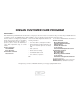
NISSAN CUSTOMER CARE PROGRAM NISSAN CARES . . . Both NISSAN and your NISSAN dealer are dedicated to serving all your automotive needs. Your satisfaction with your vehicle and your NISSAN dealer are our primary concerns. Your NISSAN dealer is always available to assist you with all your automobile sales and service needs.
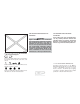
Table of Contents Illustrated table of contents 0 Safety—Seats, seat belts and supplemental restraint system 1 Instruments and controls 2 Pre-driving checks and adjustments 3 Monitor, climate, audio, phone and voice recognition systems 4 Starting and driving 5 In case of emergency 6 Appearance and care 7 Maintenance and do-it-yourself 8 Technical and consumer information 9 Index 10
0 Illustrated table of contents Air bags, seat belts and child restraints . . . . . . . . . . . . . . 0-2 Exterior front . . . . . . . . . . . . . . . . . . . . . . . . . . . . . . . . . . . . . . 0-3 Exterior rear. . . . . . . . . . . . . . . . . . . . . . . . . . . . . . . . . . . . . . . 0-4 Passenger compartment . . . . . . . . . . . . . . . . . . . . . . . . . . . 0-5 Instrument Panel . . . . . . . . . . . . . . . . . . . . . . . . . . . . . . . . . . 0-6 Engine compartment check locations . . . . .
AIR BAGS, SEAT BELTS AND CHILD RESTRAINTS 1. 2. 3. 4. Top tether strap anchor (P. 1-21) Rear head restraints/headrests (P. 1-6) Rear seat belts (P. 1-11) Roof-mounted curtain side-impact and rollover supplemental air bag (P. 1-40) 5. Front seat-mounted side-impact supplemental air bags (P. 1-40) 6. Front head restraints/headrests (P. 1-6) 7. Front seat belt with pretensioner and shoulder height adjuster (P. 1-11, 1-40) 8. Supplemental front-impact air bags (P. 1-40) 9.
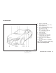
EXTERIOR FRONT 1. 2. 3. 4. 5. 6. 7. 8. 9. 10. 11. 12. 13. Engine hood (P. 3-20) Wiper and washer switch (P. 2-36) Windshield (P. 8-20) Power windows (P. 2-51) Door locks, NISSAN Intelligent Key®, keys (P. 3-3, 3-6, 3-2) Mirrors, side view camera (if so equipped) (P. 3-28, 4-9) Tire pressure (P. 8-31) Flat tire (P. 6-3) Tire chains (P. 8-31) Headlight and turn signal switch, replacing bulbs (P. 2-38, 8-27) Fog light switch (P. 2-38) Sonar sensors (if so equipped) (P.
EXTERIOR REAR 1. 2. 3. 4. 5. 6. 7. 8. Rear window defroster switch (P. 2-38) High-mounted stop light (P. 8-27) Interior trunk lid release (P. 3-21) Trunk lid (P. 3-21) Exterior trunk lid release/request button (P. 3-6) Replacing bulbs (P. 8-27) Fuel-filler door, fuel recommendation (P. 3-23, 9-2) Child safety rear door locks (P. 3-3) Refer to the page number indicated in parentheses for operating details.
PASSENGER COMPARTMENT 1. 2. Interior trunk access (P. 1-2) Power moonroof (if so equipped) (P. 2-55) 3. Sun visors (P. 3-27) 4. Map lights (P. 2-58) 5. Rearview mirror (P. 3-28) 6. HomeLink® Universal Transceiver (P. 2-60) 7. Glove box (P. 2-47) 8. Cup holders (P. 2-47) 9. Console box (P. 2-47) 10. Front seats (P. 1-2) 11. Rear seats (P. 1-2) Refer to the page number indicated in parentheses for operating details.
INSTRUMENT PANEL 1. 2. 3. 4. 5. 6. 7. 8. 9. 10. 11. 12. 13. 14. 15. 16. 17. 18. LIC3260 0-6 Illustrated table of contents Vent (P. 4-24) Headlight/fog light/turn signal switch (P. 2-38) Supplemental front-impact air bag/horn (P. 1-40, 2-42) Meters, gauges, warning lights, indicator lights and vehicle information display (P. 2-3, P. 2-7, P. 2-15) Wiper and washer switch (P. 2-36) Vent (P. 4-24) Hazard warning flasher switch (P. 6-2) Navigation controls* Front passenger supplemental air bag (P.
19. 20. 21. 22. 23. Cruise control main/Intelligent Cruise Control (ICC) (if so equipped) set switches (P. 5-40, 5-42) Hood release (P. 3-20) Fuse box (P. 8-22) Heated steering wheel switch (if so equipped) (P. 2-45) Vehicle Dynamic Control (VDC) OFF switch (P. 2-45) Trunk release switch (P. 3-21) Rear power sunshade switch (if so equipped) (P. 2-57) Instrument brightness control (P. 2-38)/Twin trip odometer reset switch (P. 2-3) * Refer to the separate Navigation System Owner’s Manual.
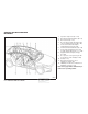
ENGINE COMPARTMENT CHECK LOCATIONS VQ35DE engine 1. 2. 3. 4. 5. 6. 7. 8. 9. 10. 11. 12. 13. Engine coolant reservoir (P. 8-8) Drive belt location (P. 8-18) Engine oil filler cap (P. 8-10) Brake fluid reservoir (P. 8-14) Air cleaner (P. 8-20) Fuse block (P. 8-22) Fuse block/Fusible links (P. 8-22) Fusible links (P. 8-22) Battery (P. 8-16) Engine oil dipstick (P.8-10) Radiator cap (P. 8-8) Power steering fluid reservoir (P. 8-14) Windshield-washer fluid reservoir (P.
WARNING AND INDICATOR LIGHTS Warning light Name Page Anti-lock Braking System (ABS) warning light Brake warning light Warning light Name Page 2-7 Master warning light 2-10 Malfunction Indicator Light (MIL) 2-12 2-8 Power steering warning light 2-11 Security indicator light 2-13 Seat belt warning light and chime 2-11 Side light and headlight indicator light (green) 2-13 Supplemental air bag warning light 2-11 Slip indicator light 2-13 Turn signal/hazard indicator lights 2-13 Vehicl
MEMO 0-10 Illustrated table of contents
1 Safety—Seats, seat belts and supplemental restraint system Seats . . . . . . . . . . . . . . . . . . . . . . . . . . . . . . . . . . . . . . . . . . . . 1-2 Front power seat adjustment. . . . . . . . . . . . . . . . . . . . . 1-3 Folding rear seat . . . . . . . . . . . . . . . . . . . . . . . . . . . . . . . 1-5 Center armrest . . . . . . . . . . . . . . . . . . . . . . . . . . . . . . . . . 1-6 Head restraints/headrests . . . . . . . . . . . . . . . . . . . . . . . . . .
SEATS ● To help avoid risk of injury or death through unintended operation of the vehicle and/or its systems, do not leave children, people who require the assistance of others or pets unattended in your vehicle. Additionally, the temperature inside a closed vehicle on a warm day can quickly become high enough to cause a significant risk of injury or death to people and pets. ARS1152 WARNING ● Do not ride in a moving vehicle when the seatback is reclined. This can be dangerous.
The reclining feature allows adjustment of the seatback for occupants of different sizes for added comfort and to help obtain proper seat belt fit. For additional information, refer to “Precautions on seat belt usage” in this section. Also, the seatback can be reclined to allow occupants to rest when the vehicle is stopped and the shift lever is in P (Park).
LRS2693 Seat lifter (driver’s seat) Push the front or rear end of the switch up or down to adjust the angle and height of the seat cushion. LRS2669 LRS2666 Lumbar support (if so equipped for driver’s seat) Thigh extension (if so equipped for driver’s seat) The lumbar support feature provides adjustable lower back support to the driver. Push the front or back end of the switch to adjust the seat lumbar area. Pull up and hold the lever to extend the front portion to the desired position.
1. Move the front passenger seat to the most forward position. 2. Open the access cover on the rear parcel shelf. 1 on the rear 3. Push down on the button 䊊 parcel shelf. 4. Fold down the passenger’s side seatback 2 . 䊊 WARNING ● Never allow anyone to ride in the cargo area or on the rear seat when it is in the fold-down position. Use of these areas by passengers without proper restraints could result in serious injury or death in an accident or sudden stop.
HEAD RESTRAINTS/HEADRESTS WARNING LRS2168 To fold down the driver side of the rear seat, open 1 . the trunk and pull on the strap 䊊 The rear seats can be locked using the mechanical key to prevent unauthorized access. For additional information on keys, refer to “Keys” in the “Pre-driving checks and adjustments” section of this manual. LRS2694 CENTER ARMREST Pull the armrest down until it rests on the seat cushion.
● Adjustable head restraints/headrests have multiple notches along the stalk(s) to lock them in a desired adjustment position. ● The non-adjustable head restraints/headrests have a single locking notch to secure them to the seat frame. ● Proper Adjustment: – For the adjustable type, align the head restraint/headrest so the center of your ear is approximately level with the center of the head restraint/headrest. LRS2695 The illustration shows the seating positions equipped with head restraints/headrests.
5. Reinstall and properly adjust the head restraint/headrest before an occupant uses the seating position. LRS2299 NON-ADJUSTABLE HEAD RESTRAINT/HEADREST COMPONENTS 1. Removable head restraint/headrest LRS2302 REMOVE Use the following procedure to remove the head restraint/headrest: 2. Single notch 1. Pull the head restraint/headrest up to the highest position. 3. Lock knob 2. Push and hold the lock knob. 4. Stalks 3. Remove the head restraint/headrest from the seat. 4.
LRS2303 INSTALL 1. Align the head restraint/headrest stalks with the holes in the seat. Make sure that the head restraint/headrest is facing the correct direction. The stalk with the notch (notches) 1 must be installed in the hole with the lock 䊊 2 .
LRS2305 LRS2306 Raise Lower To raise the head restraint/headrest, pull it up. To lower, push and hold the lock knob and push the head restraint/headrest down. Make sure the head restraint/headrest is positioned so the lock knob is engaged in the notch before riding in that designated seating position. Make sure the head restraint/headrest is positioned so the lock knob is engaged in the notch before riding in that designated seating position.
SEAT BELTS SSS0136 PRECAUTIONS ON SEAT BELT USAGE If you are wearing your seat belt properly adjusted and you are sitting upright and well back in your seat with both feet on the floor, your chances of being injured or killed in a collision and/or the severity of injury may be greatly reduced. NISSAN strongly encourages you and all of your passengers to buckle up every time you drive, even if your seating position includes a supplemental air bag. Most U.S.
SSS0134 WARNING ● Every person who drives or rides in this vehicle should use a seat belt at all times. Children should be in the rear seats and in an appropriate restraint. 1-12 Safety—Seats, seat belts and supplemental restraint system SSS0016 WARNING ● The seat belt should be properly adjusted to a snug fit. Failure to do so may reduce the effectiveness of the entire restraint system and increase the chance or severity of injury in an accident.
● Be sure the seat belt tongue is securely fastened to the proper buckle. ● Do not wear the seat belt inside out or twisted. Doing so may reduce its effectiveness. ● Do not allow more than one person to use the same seat belt. ● Never carry more people in the vehicle than there are seat belts. SSS0014 WARNING ● Always route the shoulder belt over your shoulder and across your chest. Never put the belt behind your back, under your arm or across your neck.
PREGNANT WOMEN NISSAN recommends that pregnant women use seat belts. The seat belt should be worn snug and always position the lap belt as low as possible around the hips, not the waist. Place the shoulder belt over your shoulder and across your chest. Never run the lap/shoulder belt over your abdominal area. Contact your doctor for specific recommendations. INJURED PERSONS LRS0786 SEAT BELT WARNING LIGHT Both the driver’s and passenger’s front seats are equipped with a seat belt warning light.
LRS2692 Front seat shown Fastening the seat belts 1. Adjust the seat. For additional information, refer to “Seats” in this section. LRS2674 2. Slowly pull the seat belt out of the retractor A until and insert the tongue into the buckle 䊊 you hear and feel the latch engage. ● The retractor is designed to lock during a sudden stop or on impact. A slow pulling motion permits the seat belt to move, and allows you some freedom of movement in the seat.
The ELR mode allows the seat belt to extend and retract to allow the driver and passengers some freedom of movement in the seat. The ELR locks the seat belt when the vehicle slows down rapidly or during certain impacts. The ALR mode (child restraint mode) locks the seat belt for child restraint installation. LRS2675 3. Position the lap belt portion low and snug B as shown. on the hips 䊊 4. Pull the shoulder belt portion toward the C .
To increase your confidence in the seat belts, check the operation as follows: WARNING ● After adjustment, release the adjustment button and try to move the shoulder belt anchor up and down to make sure it is securely fixed in position. ● Grasp the shoulder belt and pull forward quickly. The retractor should lock and restrict further belt movement. If the retractor does not lock during this check or if you have any questions about seat belt operation, see a NISSAN dealer.
CHILD SAFETY WARNING ● Only NISSAN seat belt extenders, made by the same company which made the original equipment seat belts, should be used with NISSAN seat belts. ● Adults and children who can use the standard seat belt should not use an extender. Such unnecessary use could result in serious personal injury in the event of an accident. ● If dirt builds up in the shoulder belt guide of the seat belt anchors, the seat belts may retract slowly. Wipe the shoulder belt guide with a clean, dry cloth.
There are three basic types of child restraint systems: ● Rear-facing child restraints ● Forward-facing child restraints ● Booster seats The proper restraint depends on the child’s size. Generally, infants up to about 1 year and less than 20 lbs (9 kg) should be placed in rear-facing child restraints. Forward-facing child restraints are available for children who outgrow rearfacing child restraints and are at least 1 year old.
Once a child outgrows the height or weight limit of the harness-equipped forward-facing child restraint, NISSAN recommends that the child be placed in a commercially available booster seat to obtain proper seat belt fit. For a seat belt to fit properly, the booster seat should raise the child so that the shoulder belt is properly positioned across the chest and the top, middle portion of the shoulder. The shoulder belt should not cross the neck or face and should not fall off the shoulder.
CHILD RESTRAINTS WARNING Never let a child stand or kneel on any seat and do not allow a child in the cargo area. The child could be seriously injured or killed in a sudden stop or collision.
– NISSAN recommends that all child restraints be installed in the rear seat. Studies show that children are safer when properly restrained in the rear seat than in the front seat. If you must install a forward-facing child restraint in the front seat, refer to “Forward-facing child restraint installation using the seat belts” in this section. – Even with the NISSAN Advanced Air Bag System, never install a rearfacing child restraint in the front seat.
● If the child restraint is compatible with your vehicle, place your child in the child restraint and check the various adjustments to be sure the child restraint is compatible with your child. Choose a child restraint that is designed for your child’s height and weight. Always follow all recommended procedures. child restraint. Be sure to follow the child restraint manufacturer’s instructions for installation.
– Inspect the lower anchors by inserting your fingers into the lower anchor area. Feel to make sure there are no obstructions over the anchors such as seat belt webbing or seat cushion material. The child restraint will not be secured properly if the lower anchors are obstructed. – Child restraint anchorages are designed to withstand only those loads imposed by correctly fitted child restraints.
The child restraint top tether strap must be used when installing the child restraint with the LATCH lower anchor attachments or seat belts. For additional information, refer to “Installing top tether strap” in this section. If you have any questions when installing a top tether strap child restraint, consult a NISSAN dealer for details. 1 are located on the rear parcel Anchor points 䊊 shelf.
Follow these steps to install a rear-facing child restraint using the LATCH system: 1. Position the child restraint on the seat. Always follow the child restraint manufacturer’s instructions. WRS0801 Rear-facing webbing-mounted – step 2 2. Secure the child restraint anchor attachments to the LATCH lower anchors. Check to make sure the LATCH attachment is properly attached to the lower anchors.
5. Check to make sure the child restraint is properly secured prior to each use. If the child restraint is loose, repeat steps 1 through 4. REAR-FACING CHILD RESTRAINT INSTALLATION USING THE SEAT BELTS WARNING LRS0673 Rear-facing – step 3 3. For child restraints that are equipped with webbing-mounted attachments, remove any additional slack from the anchor attachments.
Do not use the lower anchors if the combined weight of the child and the child restraint exceeds 65 lbs (29.5 kg). If the combined weight of the child and the child restraint is greater than 65 lbs, (29.5 kg) use the vehicle’s seat belt (not the lower anchors) to install the child restraint. Be sure to follow the child restraint manufacturer’s instructions for installation.
LRS2395 Rear-facing – step 3 3. Pull the shoulder belt until the belt is fully extended. At this time, the seat belt retractor is in the ALR mode (child restraint mode). It reverts to the ELR mode when the seat belt is fully retracted. LRS2396 Rear-facing – step 4 4. Allow the seat belt to retract. Pull up on the shoulder belt to remove any slack in the belt. WRS0762 Rear-facing – step 5 5.
7. Check to make sure that the child restraint is properly secured prior to each use. If the seat belt is not locked, repeat steps 1 through 6. After the child restraint is removed and the seat belt fully retracted, the ALR mode (child restraint mode) is canceled. FORWARD-FACING CHILD RESTRAINT INSTALLATION USING LATCH LRS2397 Rear-facing – step 6 6. After attaching the child restraint, test it before you place the child in it.
If the seating position does not have an adjustable head restraint/headrest and it is interfering with the proper child restraint fit, try another seating position or a different child restraint. WRS0800 Forward-facing rigid-mounted – step 2 3. The back of the child restraint should be secured against the vehicle seatback. If necessary, adjust or remove the head restraint/headrest to obtain the correct child restraint fit. If the head restraint/headrest is removed, store it in a secure place.
7. Check to make sure the child restraint is properly secured prior to each use. If the child restraint is loose, repeat steps 1 through 6. WRS0697 Forward-facing – step 6 6. After attaching the child restraint, test it before you place the child in it. Push it from side to side while holding the child restraint near the LATCH attachment path. The child restraint should not move more than 1 inch (25 mm), from side to side.
Rear bench seat 1. Remove the head restraint/headrest and store it in a secure place. Be sure to reinstall the head restraint/headrest when the child restraint is removed. For additional information about head restraint/headrest adjustment, removal and installation, refer to “Head restraints/headrests” in this section. 1 over the 2. Position the top tether strap 䊊 seatback. 3. Secure the tether strap to the tether anchor 2 on the rear-parcel shelf behind the point 䊊 child restraint. 4.
Follow these steps to install a forward-facing child restraint using the vehicle seat belt in the rear seats or in the front passenger seat: 1. If you must install a child restraint in the front seat, it should be placed in a forward-facing direction only. Move the seat to the rearmost position. Child restraints for infants must be used in the rear-facing direction and therefore must not be used in the front seat.
LRS0667 Forward-facing – step 4 4. Pull the shoulder belt until the belt is fully extended. At this time, the seat belt retractor is in the ALR mode (child restraint mode). It reverts to ELR mode when the seat belt is fully retracted. LRS0668 Forward-facing – step 5 5. Allow the seat belt to retract. Pull up on the shoulder belt to remove any slack in the belt. WRS0681 Forward-facing – step 6 6.
9. Check to make sure the child restraint is properly secured prior to each use. If the seat belt is not locked, repeat steps 3 through 8. WRS0698 Forward-facing – step 8 8. After attaching the child restraint, test it before you place the child in it. Push it from side to side while holding the child restraint near the seat belt path. The child restraint should not move more than 1 inch (25 mm), from side to side. Try to tug it forward and check to see if the belt holds the restraint in place.
tion about head restraint/headrest adjustment, removal and installation, refer to “Head restraints/headrests” in this section. 1 over the 2. Position the top tether strap 䊊 seatback. 3. Secure the tether strap to the tether anchor 2 on the rear-parcel shelf behind the point 䊊 child restraint. 4. Tighten the tether strap according to the manufacturer’s instructions to remove any slack.
LRS2479 A. Low back booster seat B. High back booster seat LRS0453 LRS0464 Booster seats of various sizes are offered by several manufacturers. When selecting any booster seat, keep the following points in mind: ● Make sure the child’s head will be properly supported by the booster seat or vehicle seat. The seatback must be at or above the center of the child’s ears. For example, if a low back booster seat is chosen, the vehicle seatback must be at or above the center of the child’s ears.
All U.S. states and Canadian provinces or territories require that infants and small children be restrained in an approved child restraint at all times while the vehicle is being operated. The instructions in this section apply to booster seat installation in the rear seats or the front passenger seat. Booster seat installation CAUTION To avoid injury to child, do not use the lap/shoulder belt in the Automatic Locking Retractor (ALR) mode when using a booster seat with the seat belts.
SUPPLEMENTAL RESTRAINT SYSTEM (SRS) If the seating position does not have an adjustable head restraint/headrest and it is interfering with the proper booster seat fit, try another seating position or a different booster seat. PRECAUTIONS ON SRS This SRS section contains important information concerning the following systems: ● Driver and front passenger supplemental front-impact air bag (NISSAN Advanced Air Bag System) 4. Position the lap portion of the seat belt low and snug on the child’s hips.
Roof-mounted curtain side-impact and rollover supplemental air bag system This system can help cushion the impact force to the head of occupants in front and rear outboard seating positions in certain side-impact or rollover collisions. In a side impact, the curtain air bags are designed to inflate on the side where the vehicle is impacted. In a rollover, curtain air bags on both sides are designed to inflate and remain inflated for a short time.
● The driver and front passenger seat belt buckles are equipped with sensors that detect if the seat belts are fastened. The NISSAN Advanced Air Bag System monitors the severity of a collision and seat belt usage then inflates the air bags as needed. Failure to properly wear seat belts can increase the risk or severity of injury in an accident. ● The front passenger seat is equipped with an occupant classification sensor (weight sensor) that turns the front passenger air bag OFF under some conditions.
ARS1041 ARS1042 ● Never let children ride unrestrained or extend their hands or face out of the window. Do not attempt to hold them in your lap or arms. Some examples of dangerous riding positions are shown in the illustrations ● Children may be severely injured or killed when the front air bags, side air bags or curtain air bags inflate if they are not properly restrained. Pre-teens and children should be properly restrained in the rear seat, if possible.
ARS1044 ARS1045 WRS0256 WARNING ● Even with the NISSAN Advanced Air Bag System, never install a rear-facing child restraint in the front seat. An inflating front air bag could seriously injure or kill your child. For additional information, refer to “Child restraints” in this section.
WARNING SSS0101 WARNING SSS0188 ● The seat belts, the side air bags and curtain air bags are most effective when you are sitting well back and upright in the seat with both feet on the floor. The side air bag and curtain air bag inflate with great force. Do not allow anyone to place their hand, leg or face near the side air bag on the side of the seatback of the front seat or near the side roof rails.
WRS0032 WARNING ● When sitting in the rear seat, do not hold onto the seatback of the front seat. If the side air bag inflates, you may be seriously injured. Be especially careful with children, who should always be properly restrained. Some examples of dangerous riding positions are shown in the illustrations. ● Do not use seat covers on the front seatbacks. They may interfere with side air bag inflation.
5. Supplemental front-impact air bag modules 6. Crash zone sensor 7. Occupant classification system control unit 8. Occupant classification sensor (weight sensor) 9. Seat belt buckle switches for driver’s and front passenger’s side 10. Seat belt with pretensioners (front seats) 11. Side satellite sensors WARNING To ensure proper operation of the passenger’s NISSAN Advanced Air Bag System, please observe the following items.
● Do not position the front passenger seat so it contacts the rear bench seats. If the front seat does contact the rear bench seats, the air bag system may determine a sensor malfunction has occurred and the front passenger air bag status light may illuminate and the supplemental air bag warning light may flash. ● If a forward-facing child restraint is installed in the front passenger seat, do not position the front passenger seat so the child restraint contacts the instrument panel.
cause irritation and choking. Those with a history of a breathing condition should get fresh air promptly. Front air bags, along with the use of seat belts, help to cushion the impact force on the face and chest of the front occupants. They can help save lives and reduce serious injuries. However, an inflating front air bag may cause facial abrasions or other injuries. Front air bags do not provide restraint to the lower body.
In addition to the above, certain objects placed on the front passenger seat may also cause the light to operate as described above depending on their weight. For additional information related to the normal operation and troubleshooting of this occupant classification sensor system, please refer to “Normal operation” and “Troubleshooting” in this section.
used. If the air bag status light is not illuminated (indicating that the air bag might inflate in a crash), it could be that the child restraint or seat belt is not being used properly. Make sure that the child restraint is installed properly, the seat belt is used properly and the occupant is positioned properly. If the air bag status light is still not illuminated, reposition the occupant or child restraint in a rear seat.
NOTE: ● Forcing the front seat or seatback against an object on the seat or floor behind it. This vehicle’s occupant classification sensor system locks the classification during driving so it is important that you confirm that the front passenger is properly classified prior to driving. Also, the occupant classification sensor system may recalculate the weight of the occupant when the vehicle comes to a stop (i.e. stop light, stop sign, etc.
NOTE: A system check will be performed during which the front passenger air bag status light will remain lit for about 7 seconds initially. If the light is still ON after this, the person should be advised not to ride in the front passenger seat and the vehicle should be checked by a NISSAN dealer as soon as possible. 3. If the light is OFF with a small adult, child or child restraint occupying the front passenger seat.
● Tampering with the front air bag system may result in serious personal injury. Tampering includes changes to the steering wheel and the instrument panel assembly by placing material over the steering wheel pad and above the instrument panel or by installing additional trim material around the air bag system. ● Removing or modifying the front passenger seat may affect the function of the air bag and result in serious personal injury.
the side where the vehicle is impacted. They may not inflate in certain side collisions. Curtain air bags are also designed to inflate in certain types of rollover collisions or near rollovers. As a result, certain vehicle movements (for example, during severe off-roading) may cause the curtain air bags to inflate. Vehicle damage (or lack of it) is not always an indication of proper side air bag and curtain air bag operation.
● Tampering with the side air bag system may result in serious personal injury. For example, do not change the front seats by placing material near the seatbacks or by installing additional trim material, such as seat covers, around the side air bag. ● Work around and on the side air bag and curtain air bag systems should be done by a NISSAN dealer. Installation of electrical equipment should also be done by a NISSAN dealer. The SRS wiring harnesses* should not be modified or disconnected.
The supplemental air bag warning light is used to indicate malfunctions in the pretensioner system. For additional information, refer to ⬙Supplemental air bag warning light⬙ in this section. If the operation of the supplemental air bag warning light indicates there is a malfunction, have the system checked by a NISSAN dealer. When selling your vehicle, we request that you inform the buyer about the pretensioner system and guide the buyer to the appropriate sections in this Owner’s Manual. LRS2699 1.
If any of the following conditions occur, the front air bag, side air bag, curtain air bag and pretensioner systems need servicing: ● The supplemental air bag warning light remains on after approximately 7 seconds. ● The supplemental air bag warning light flashes intermittently. ● The supplemental air bag warning light does not come on at all. Under these conditions, the front air bag, side air bag, curtain air bag or pretensioner systems may not operate properly. They must be checked and repaired.
MEMO Safety—Seats, seat belts and supplemental restraint system 1-59
2 Instruments and controls Instrument Panel . . . . . . . . . . . . . . . . . . . . . . . . . . . . . . . . . . 2-2 Meters and gauges . . . . . . . . . . . . . . . . . . . . . . . . . . . . . . . . 2-3 Speedometer and odometer . . . . . . . . . . . . . . . . . . . . . 2-4 Tachometer . . . . . . . . . . . . . . . . . . . . . . . . . . . . . . . . . . . . 2-5 Engine coolant temperature gauge . . . . . . . . . . . . . . . 2-5 Fuel gauge . . . . . . . . . . . . . . . . . . . . . . . . . . . . . . . . . . . .
Extended storage switch . . . . . . . . . . . . . . . . . . . . . . . . . . 2-46 Storage . . . . . . . . . . . . . . . . . . . . . . . . . . . . . . . . . . . . . . . . . 2-47 Map pockets . . . . . . . . . . . . . . . . . . . . . . . . . . . . . . . . . . 2-47 Seatback pockets . . . . . . . . . . . . . . . . . . . . . . . . . . . . . 2-47 Sunglasses holder . . . . . . . . . . . . . . . . . . . . . . . . . . . . . 2-48 Cup holders . . . . . . . . . . . . . . . . . . . . . . . . . . . . . . . . . .
INSTRUMENT PANEL 1. 2. 3. 4. 5. 6. 7. 8. 9. 10. 11. 12. 13. 14. 15. 16. 17. 18. LIC3260 2-2 Instruments and controls Vent (P. 4-24) Headlight/fog light/turn signal switch (P. 2-38) Supplemental front-impact air bag/horn (P. 1-40, 2-42) Meters, gauges, warning lights, indicator lights and vehicle information display (P. 2-3, P. 2-7, P. 2-15) Wiper and washer switch (P. 2-36) Vent (P. 4-24) Hazard warning flasher switch (P. 6-2) Navigation controls* Front passenger supplemental air bag (P. 2-34) Vent (P.
METERS AND GAUGES 19. 20. 21. 22. 23. Cruise control main/Intelligent Cruise Control (ICC) (if so equipped) set switches (P. 5-40, 5-42) Hood release (P. 3-20) Fuse box (P. 8-22) Heated steering wheel switch (if so equipped) (P. 2-45) Vehicle Dynamic Control (VDC) OFF switch (P. 2-45) Trunk release switch (P. 3-21) Rear power sunshade switch (if so equipped) (P. 2-57) Instrument brightness control (P. 2-38)/Twin trip odometer reset switch (P.
SPEEDOMETER AND ODOMETER This vehicle is equipped with a speedometer and odometer. The speedometer is located on the right side of the meter cluster. The odometer is located within the vehicle information display. LIC3116 Changing the display The speedometer indicates vehicle speed.
CAUTION If the gauge indicates coolant temperature near the hot (H) end of the normal range, reduce vehicle speed to decrease temperature. If the gauge is over the normal range, stop the vehicle as soon as safely possible. If the engine is overheated, continued operation of the vehicle may seriously damage the engine. For additional information, refer to “If your vehicle overheats” in the “In case of emergency” section of this manual for immediate action required.
Refill the fuel tank before the gauge registers 0 (Empty). indicates that the fuel-filler door is The located on the driver’s side of the vehicle. CAUTION ● If the vehicle runs out of fuel, the Malfunction Indicator Light (MIL) may come on. Refuel as soon as possible. light After a few driving trips. the should turn off. If the light remains on after a few driving trips, have the vehicle inspected by a NISSAN dealer. LIC2222 FUEL GAUGE The gauge indicates the approximate fuel level in the tank.
WARNING LIGHTS, INDICATOR LIGHTS AND AUDIBLE REMINDERS Anti-lock Braking System (ABS) warning light Power steering warning light Security indicator light or Seat belt warning light and chime Side light and headlight indicator light (green) Charge warning light Supplemental air bag warning light Slip indicator light Engine oil pressure warning light Front fog light indicator light Turn signal/hazard indicator lights Forward emergency braking system warning light (if so equipped) Front passenger
If the ABS warning light illuminates while the engine is running or while driving, it may indicate the ABS is not functioning properly. Have the system checked by a NISSAN dealer. If an ABS malfunction occurs, the anti-lock function is turned off. The brake system then operates normally but without anti-lock assistance. For additional information, refer to “Brake system” in the “Starting and driving” section of this manual.
CAUTION Running the engine with the engine oil pressure warning light on could cause serious damage to the engine almost immediately. Such damage is not covered by warranty. Turn off the engine as soon as it is safe to do so. Forward Emergency Braking (FEB) system warning light (if so equipped) This light illuminates when the Forward Emergency Braking system is set to OFF on the meter display.
WARNING ● Radio waves could adversely affect electric medical equipment. Those who use a pacemaker should contact the electric medical equipment manufacturer for the possible influences before use. ● If the light does not illuminate with the ignition switch placed in the ON position, have the vehicle checked by a NISSAN dealer as soon as possible.
● Parking Brake ON (RED) ● Low Washer Fluid ● I-Key System Fault ● Low Tire Pressure ● CVT Warning ● Sonar Parking Sensor Error ● LED Headlight Failure (RED if no other red warnings are active) ● Chassis Control warning ● Driver Attention Alert System Fault ● Emergency Assist Pedal System Fault For additional information, refer to “vehicle information display” in this section.
Unless checked and repaired, the supplemental restraint system (air bag system) and/or the seat belts with pretensioner system may not function properly. For additional information, refer to “Supplemental restraint system (SRS)” in the “Safety—Seats, seat belts and supplemental restraint system” section of this manual. WARNING If the supplemental air bag warning light is on, it could mean that the front air bag, side air bag, curtain air bag, and/or pretensioner systems will not operate in an accident.
Operation The MIL will come on in one of two ways: ● MIL on steady — An emission control system malfunction has been detected. Check the fuel-filler cap if the LOOSE FUEL CAP warning appears in the vehicle information display. If the fuel-filler cap is loose or missing, tighten or install the cap and continue to light should turn drive the vehicle. The light off after a few driving trips. If the does not turn off after a few driving trips, have the vehicle inspected by a NISSAN dealer.
Vehicle Dynamic Control (VDC) OFF indicator light This indicator light comes on when the VDC off switch is pushed to OFF. This indicates the VDC system is not operating. Push the VDC off switch again or restart the engine and the system will operate normally. For additional information, refer to “Vehicle Dynamic Control (VDC) system” in the “Starting and driving” section of this manual. The VDC light also comes on when you place the ignition switch in the ON position.
VEHICLE INFORMATION DISPLAY ● Sport Information (Oil pressure, Gear Oil Temperature, Digital Speedometer, Horsepower) ● Indicators and Warnings ● Vehicle and Meter Display Settings ● Cruise Control Status ● Odometer/twin trip odometer ● Gear Position Indicator (P, R, N, D) ● Distance To Empty and Fuel Indicator LIC3224 The vehicle information display is located to the left of the speedometer.
3 䊊 — Scroll up or down the vehicle information menu items. If the vehicle information display is not showing a menu with buttons, pressing the or will change to the previous/next audio preset. 4 䊊 — go back or forward through the vehicle information menu items or to change from one display screen to the next. and buttons also The OK, control audio and control panel functions in some conditions.
SETTINGS ● Emergency Brake (if so equipped) ● Navigation The setting mode allows you to change the information displayed in the vehicle information display as well as the model for several vehicle functions: ● Driver Attention Alert (if so equipped) ON/OFF ● Drive computer ● Timer Alert ● Driver Assistance ● Low Temperature Alert ON/OFF ● Customize Display ● Integrated Dynamics-control Module - Active Trace Control ON/OFF (if so equipped) ● Vehicle Settings ● Maintenance ● Clock ● TPMS Settings ●
● View History - Select to display the vehicle’s recorded fuel economy information history. To reset the information, press the OK button and confirm the reset by pressing the OK button again when prompted. Navigation Settings This setting allows the customer to configure the navigation options in the vehicle information display as well as the navigation display mode in the meter. 1. Use the Setting”. buttons to select “Navigation 2.
● Selective Unlock — When this item is turned on and when the door handle request switch on the driver’s or front passenger’s side door is pushed, only the corresponding door is unlocked first. The remaining doors will be unlocked if the door unlock operation is performed again within 1 minute. When this item is turned off, all the doors will be unlocked after the door unlock operation is performed once. From the Vehicle Settings menu, select “Locking” then “Selective Unlock”.
Other Other maintenance items can include such things as air filter or tire rotation. The distance for checking or replacing the items can be set or reset. Clock to the separate Navigation Owner’s Manual. Use buttons to choose from the following the menu options: ● Mileage/Fuel ● Tire Pressure Unit ● Temperature For additional information, refer to the separate Navigation Owner’s Manual.
Key-Linked Settings The Key-Linked Setting can be turned ON/OFF using the OK button. It will display the key synchronized and in use for this vehicle. key is detected, turn ignition to OFF, press the door lock or unlock button on the desired key, and restart the vehicle. Factory Reset The settings in the vehicle information display can be reset back to the factory default.
LIC3244 2-22 Instruments and controls
18. Driver Attention Alert Malfunction (if so equipped) 35. Intelligent Cruise Control (ICC) system ON indicator (if so equipped) 19. Alarm - Time for a break? (if so equipped) 36. SPORT 2. No Key Detected 20. Driver Attention Alert - Take a Break? (if so equipped) 37. Outside Temperature Display 3. Shift to Park 21. Illumination Brightness Control 4. Key Battery Low 22. Shipping Mode On Push Storage Fuse (if so equipped) VEHICLE INFORMATION DISPLAY WARNINGS AND INDICATORS 1.
is not in P (Park) position. Also, a chime sounds when the ignition switch is in the ACC or OFF position. If this warning illuminates, move the shift lever to the P (Park) position and start the engine. Key Battery Low This indicator illuminates when the Intelligent Key battery is running out of power. If this indicator illuminates, replace the battery with a new one. For additional information, refer to “Battery replacement” in the “Maintenance and do-it-yourself” section of this manual.
Headlight System Error: See Owner’s Manual This warning illuminates when there is an error with the system. For additional information, refer to “Headlight and turn signal switch” in this section. Tire Pressure Low - Add Air This warning appears when the low tire pressure warning light in the meter illuminates and low tire pressure is detected. The warning appears each time the ignition switch is placed in the ON position as long as the low tire pressure warning light remains illuminated.
Reminder: Turn OFF headlights Tire This warning appears when the headlights are left in the ON position when exiting the vehicle. Place the headlight switch in the OFF or AUTO position. For additional information, refer to “Headlight and turn signal switch” in this section. This indicator appears when the customer set distance is reached for replacing tires. You can set or reset the distance for replacing tires.
CONTROL PANEL AND VEHICLE INFORMATION DISPLAY INTERACTION BSW/RCTA System Malfunction: See Owner’s Manual (if so equipped) This warning appears when the Blind Spot Warning/Rear Cross Traffic Alert systems are not functioning properly. For additional information, refer to “Blind Spot Warning system” and “Rear Cross Traffic Alert (RCTA) system” in the “Starting and driving” section of this manual.
RECEIVING A CALL Using Bluetooth® Hands-Free Phone System, a received phone call can be operated on the vehicle information display as well as on the touchscreen display. 1. When there is an incoming call, the caller information and the operation keys are displayed on the vehicle information display. or to highlight the pre2. Use ferred item and push the OK button to select the item. 2-28 Instruments and controls Available keys [Answer] [Decline] Action Answers the received phone call.
TEXT MESSAGING Using Bluetooth® Hands-Free Phone System, a received text message can be operated on the vehicle information display as well as on the touch-screen display. Available keys [Read] [Ignore] Action View or hear the received message. Ignore the received message. To read/ignore an incoming text 1. When a new text message is received, a pop-up window and operation keys will appear with the sender’s name or phone number on the vehicle information display. or to highlight the pre2.
To reply to/exit from a text Available keys 1. When a new text message is received and [Read] is selected, operation keys are displayed on the vehicle information display. [Reply] or to highlight the pre2. Use ferred item and push the OK button to select the item. [Exit] Action Available pre-determined messages will be displayed on the vehicle information display if the steering switch controls are used.
NAVIGATION SYSTEM Turn-by-turn route guidance can be displayed on the vehicle information display. To view turn-by-turn route guidance on the veor and hicle information display, use scroll to on the vehicle information display menu. LIC3228 LIC3163 City view Arrow view City view shows representation of intersections with road curvature and surroundings. Lane guidance will appear in the lower right corner, if the data is available for that street.
Navigation settings The navigation related display settings can be changed. using or and 1. Select push the OK button A menu will display. or , select [Customize 2. Using Display] and then select [Navigation Settings]. 3. Select the preferred item using or . LIC3229 LIC3230 Compass view Far screen view Compass view is displayed when no route is set, and shows current weather conditions and speed limit information (if available).
Available items [Alerts] [Arrow view] [City view] Action When this item is turned on, the view of the turning point with an alarm sound will interrupt the displays other than navigation screen when the vehicle approaches the guide point. When this mode is selected, the Arrow view will be displayed on the vehicle information display. When this mode is selected, the view on the vehicle information display will switch from the Arrow view to the City view as the vehicle approaches a guide point. 4.
SECURITY SYSTEMS The icon will not move across the screen if the vehicle is moving over speeds of 7 kph (4 mph), yet the information will still transfer to the vehicle information display. The system helps deter vehicle theft but cannot prevent it, nor can it prevent the theft of interior or exterior vehicle components in all situations. Always secure your vehicle even if parking for a brief period. Never leave your Intelligent Key in the vehicle, and always lock the vehicle when unattended.
4. Confirm that the security indicator light stays on for about 30 seconds. The vehicle security system is now pre-armed. The vehicle security system will automatically shift into the armed phase. The security light begins to flash once every three seconds. If during the pre-armed phase one of the following occurs, the system will not arm: Vehicle security system activation Never leave these keys in the vehicle.
WIPER AND WASHER SWITCH WIC2748 LIC0474 Type A (if so equipped) Security indicator light The security indicator light blinks whenever the ignition switch is placed in the OFF, LOCK or ACC position. This function indicates the NISSAN Vehicle Immobilizer System is operational. If the NISSAN Vehicle Immobilizer System is malfunctioning, the light will remain on while the ignition switch is placed in the ON position.
– High — High sensitive operation CAUTION – Low — Low sensitive operation ● Do not operate the washer continuously for more than 30 seconds. To turn the rain-sensing auto wiper system off, push up the lever to the OFF position, or pull down the lever to the LO or HI position. ● Do not operate the washer if the windshield-washer fluid reservoir is empty. ● Do not fill the windshield-washer fluid reservoir with windshield-washer fluid concentrates at full strength.
REAR WINDOW AND OUTSIDE MIRROR (if so equipped) DEFROSTER SWITCH HEADLIGHT AND TURN SIGNAL SWITCH ● When the windshield glass is coated with water repellent, the speed of the rain-sensing auto wipers may be higher even though the amount of the rainfall is small. ● Be sure to turn off the rain-sensing auto wiper system when you use a car wash. ● The rain-sensing auto wipers may not operate if rain does not hit the rain sensor even if it is raining.
To turn on the autolight system: CAUTION 1. Turn the headlight switch to the AUTO posi1 . tion 䊊 Use the headlights with the engine running to avoid discharging the vehicle battery. 2. Turn the ignition key to ON. 3. The autolight system automatically turns the headlights on and off. Initially, if the ignition switch is turned OFF and a door is opened and left open, the headlights remain ON for a period of time. If another door is opened while the headlights are on, then the timer is reset.
CAUTION Even though the battery saver feature automatically turns off the headlights after a period of time, you should turn the headlight switch to the OFF position when the engine is not running to avoid discharging the vehicle battery. DAYTIME RUNNING LIGHT SYSTEM WHA1170 Be sure you do not put anything on top of the autolight sensor located in the top side of the instrument panel.
WARNING When the daytime running light system is active, tail lights on your vehicle are not on. It is necessary at dusk to turn on your headlights. Failure to do so could cause an accident injuring yourself and others. LIC3176 LIC3193 INSTRUMENT BRIGHTNESS CONTROL TURN SIGNAL SWITCH Press the “+” button to increase the brightness of instrument panel lights. 1 䊊 Press the “-” button to decrease the brightness of instrument panel lights.
HORN Lane change signal 2 䊊 Move the lever up or down until the turn signal begins to flash, but the lever does not latch, to signal a lane change. Hold the lever until the lane change is completed. Move the lever up or down until the turn signal begins to flash, but the lever does not latch, and release the lever. The turn signal will automatically flash three times. Choose the appropriate method to signal a lane change based on road and traffic conditions.
HEATED SEATS (if so equipped) WARNING Do not use or allow occupants to use the seat heater if you or the occupants cannot monitor elevated seat temperatures or have an inability to feel pain in body parts that contact the seat. Use of the seat heater by such people could result in serious injury. ● When cleaning the seat, never use gasoline, benzine, thinner, or any similar materials.
CLIMATE CONTROL SEAT SWITCH (if so equipped) mately 60 seconds after turning the switch on or selecting the desired temperature. 4. When the vehicle’s interior is warmed or cooled, or before you leave the vehicle, be sure to turn the control knob to the Off B on (center) position. The indicator light 䊊 the control knob goes off with the switch in the off (center) position. To check the air filter for the climate controlled seat, contact a NISSAN dealer.
HEATED STEERING WHEEL (if so equipped) VEHICLE DYNAMIC CONTROL (VDC) OFF SWITCH NOTE: If the surface temperature of the steering wheel is above 68°F (20°C) when the switch is turned on, the system will not heat the steering wheel. This is not a malfunction. LIC0421 LIC1548 The heated steering wheel system is designed to operate only when the surface temperature of the steering wheel is below 68°F (20°C). The vehicle should be driven with the VDC system on for most driving conditions.
POWER OUTLET EXTENDED STORAGE SWITCH ● Only certain power outlets are designed for use with a cigarette lighter unit. Do not use any other power outlet for an accessory lighter. See a NISSAN dealer for additional information. ● Do not use with accessories that exceed a 12 volt, 120W (10A) power draw. ● Do not use double adapters or more than one electrical accessory. ● Use power outlets with the engine running to avoid discharging the vehicle battery.
STORAGE LIC3266 LIC3268 MAP POCKETS LIC3181 SEATBACK POCKETS The seatback pockets are located on the back of the driver’s and passenger’s seats. The pockets can be used to store maps. WARNING To ensure proper operation of the passenger’s NISSAN Advanced Air Bag System, please observe the following items: ● Do not allow a passenger in the rear seat to push or pull on the seatback pocket or head restraint/headrest.
CAUTION ● Do not use for anything other than sunglasses. ● Do not leave sunglasses in the sunglasses holder while parking in direct sunlight. The heat may damage the sunglasses. LIC0016 ● Do not place heavy loads heavier than 2.2 lbs. (1 kg) on the seatback, head restraint/headrest or in the seatback pocket. LIC2312 SUNGLASSES HOLDER To open the sunglasses holder, push and release. Only store one pair of sunglasses in the holder.
LIC3182 Front cup holders CUP HOLDERS CAUTION ● Avoid abrupt starting and braking when the cup holder is being used to prevent spilling the drink. If the liquid is hot, it can scald you or your passenger. Spilled liquid can also damage the seat climate system. LIC2915 Rear cup holders LIC3183 Bottle holder — front CAUTION ● Do not use bottle holder for any other objects that could be thrown about in the vehicle and possibly injure people during sudden braking or an accident.
LIC3184 Bottle holder — rear LIC3186 Storage Tray STORAGE TRAYS WARNING Do not place sharp objects in the trays to help prevent injury in an accident or sudden stop. LIC2429 GLOVE BOX Open the glove box by pulling the handle. Use the master key when locking or unlocking the glove box. There is a trunk cancel switch in the glove box. For additional information, refer to “Cancel switch” in the “Pre-driving checks and adjustments” section of this manual.
WINDOWS POWER WINDOWS WARNING ● Make sure that all passengers have their hands, etc. inside the vehicle while it is in motion and before closing the windows. Use the window lock switch to prevent unexpected use of the power windows. WIC1504 CONSOLE BOX 1 To open the console box, press in on the lever 䊊 2 . and raise the lid 䊊 To close, push the lid down until the lock latches.
The driver’s side control panel is equipped with switches to open or close all of the windows. To open a window, push the switch and continue to hold it down until the desired window position is reached. To close a window, pull the switch and continue to hold it up until the desired window position is reached. LIC3238 Driver’s side power window switch 1. Window lock button 2. Power door lock switch 3. Front passenger side automatic switch 4. Right rear passenger side 5. Left rear passenger side 6.
Auto-reverse function If the control unit detects something caught in an automatic operation window as it is closing, the window will be immediately lowered. The auto-reverse function may be activated when the window is closed by automatic operation when the ignition switch is placed in the ON position or for a period of time after the ignition switch is placed in the OFF position.
MOONROOF (if so equipped) To open or close the moonroof part way, push the switch in any direction while the moonroof is sliding to stop it in the desired position. If the windows do not close automatically If the power window automatic function (closing only) does not operate properly, perform the following procedure to initialize the power window system. Tilting the moonroof Close the moonroof by pushing the switch to2 . Release the switch, then push the ward 䊊 2 again to tilt the moonroof up.
DUAL PANEL MOONROOF (if so equipped) Auto-reverse function (when closing or tilting down the moonroof) The auto-reverse function can be activated when the moonroof is closed or tilted down by automatic operation when the ignition switch is placed in the ON position or for a period of time after the ignition switch is placed in the OFF position.
Sliding the moonroof To slide the moonroof: ● To fully open the moonroof, push the switch 1 toward the open position until it reaches 䊊 1 is the second detent. If the switch 䊊 pushed to the first detent, only the sunshade will open. ● To fully close the moonroof, push the switch 2 toward the close position until it reaches 䊊 2 is the second detent. If the switch 䊊 pushed to the first detent, the moonroof will close but the sunshade will remain open.
REAR POWER SUNSHADE (if so equipped) To close the sunshade: ● To fully close the sunshade, push the switch 2 toward the close position until it reaches 䊊 the second detent. 2 to the first detent will ● Pushing the switch 䊊 close the moonroof only. If the moonroof does not close Have a NISSAN dealer check and repair the moonroof. LIC2644 Sunshade To open the sunshade: ● To fully open the sunshade, push the switch 1 toward the open position until it reaches 䊊 the first detent.
INTERIOR LIGHTS ● Do not hang any object on the arm rail as this may result in improper operation or damage the screen. ● Do not forcefully pull the screen. Doing so may elongate the screen. Improper operation or damage to the screen may result. ● To avoid personal injury, keep your hands, fingers and head away from the sun shade arm, arm rail and screen inlet port. LIC3231 CAUTION ● Do not place objects (such as newspapers, handkerchiefs, etc.) on the screen inlet port.
The lights will go off when the ignition switch is placed in the ON position, or the driver’s door is closed and locked. The lights will also go off after a period of time when the doors are open. NOTE: The step lights illuminate when the driver and passenger doors are opened regardless of the interior light switch position. These lights will turn off automatically after a period of time while doors are open to prevent the battery from becoming discharged.
TRUNK LIGHT HOMELINK® UNIVERSAL TRANSCEIVER The light illuminates when the trunk lid is opened. When the trunk lid is closed, the light goes off. For additional information, refer to “Exterior and interior lights” in the “Maintenance and do-ityourself” section of this manual. The HomeLink® Universal Transceiver provides a convenient way to consolidate the functions of up to three individual hand-held transmitters into one built-in device.
1. Position the end of your hand-held transmitter 5–14 cm (1–3 inches) away from the HomeLink® surface, keeping the 1 in view. HomeLink® indicator light 䊊 WARNING ● Do not use the HomeLink® Universal Transceiver with any garage door opener that lacks safety stop and reverse features as required by federal safety standards. (These standards became effective for opener models manufactured after April 1, 1982).
Do not stand on your vehicle to perform the next steps. 4. At the receiver located on the garage door opener motor in the garage, locate the “learn” or “smart” button (the name and color of the button may vary by manufacturer but it is usually located near where the hanging antenna wire is attached to the unit). If there is difficulty locating the button, reference the garage door opener’s manual. 5. Press and release the “learn” or “smart” button. LIC2365 LIC2366 2.
PROGRAMMING HOMELINK® FOR CANADIAN CUSTOMERS AND GATE OPENERS Canadian radio-frequency laws require transmitter signals to “time-out” (or quit) after several seconds of transmission – which may not be long enough for HomeLink® to pick up the signal during training. Similar to this Canadian law, some U.S. gate operators are designed to “timeout” in the same manner.
CLEARING THE PROGRAMMED INFORMATION The following procedure clears the programmed information from both buttons. Individual buttons cannot be cleared. However, individual buttons can be reprogrammed. For additional information, refer to “Reprogramming a single HomeLink® button” in this section. To clear all programming: 1. Press and hold the two outer HomeLink® buttons until the indicator light begins to flash in approximately 10 seconds. Do not hold for longer than 20 seconds. 2. Release both buttons.
3 Pre-driving checks and adjustments Keys . . . . . . . . . . . . . . . . . . . . . . . . . . . . . . . . . . . . . . . . . . . . . 3-2 NISSAN Intelligent Key® . . . . . . . . . . . . . . . . . . . . . . . . 3-2 Doors . . . . . . . . . . . . . . . . . . . . . . . . . . . . . . . . . . . . . . . . . . . . 3-3 Locking with key. . . . . . . . . . . . . . . . . . . . . . . . . . . . . . . . 3-4 Locking with inside lock knob . . . . . . . . . . . . . . . . . . . . 3-5 Locking with power door lock switch . . . .
KEYS erasing all memory in the Intelligent Key components when registering new keys, be sure to take all Intelligent Keys that you have to the NISSAN dealer. A key number plate is supplied with your keys. Record the key number and keep it in a safe place (such as your wallet), not in the vehicle. If you lose your keys, see a NISSAN dealer for duplicates by using the key number. NISSAN does not record key numbers so it is very important to keep track of your key number plate. LPD2346 1. 2. 3.
DOORS CAUTION Always carry the mechanical key installed in the Intelligent Key slot. For additional information, refer to “Doors” in this section and “Storage” in the “Instruments and controls” section of this manual. Valet hand-off When you have to leave a key with a valet, give them the Intelligent Key itself and keep the mechanical key with you to protect your belongings. SPA1951 Mechanical key The Intelligent Key contains the mechanical key, which can be used in case of a discharged battery.
Opening and closing windows The driver’s door key operation allows you to open and close windows equipped with automatic operation at the same time. ● To open the windows, turn the driver’s door key toward the rear of the vehicle for longer than 1 second after the door is unlocked. ● To close the windows, turn the driver’s door key toward the front of the vehicle for longer than 1 second after the door is locked. Windows stop when the key cylinder is released.
Lockout protection When the power door lock switch (driver’s or front passenger’s side) is moved to the lock position with the Intelligent Key left in the vehicle and any door open, all doors will unlock automatically and a chime will sound after the door is closed. AUTOMATIC DOOR LOCKS ● All doors lock automatically when the vehicle speed reaches 15 MPH (24 km/h).
NISSAN INTELLIGENT KEY® WARNING ● Radio waves could adversely affect electric medical equipment. Those who use a pacemaker should contact the electric medical equipment manufacturer for the possible influences before use. LPD2117 CHILD SAFETY REAR DOOR LOCK Child safety locks help prevent the rear doors from being opened accidentally, especially when small children are in the vehicle. The child safety lock levers are located on the edge of the rear doors.
NOTE: In such cases, correct the operating conditions before using the Intelligent Key function or use the mechanical key. If all doors are already unlocked, opening the trunk does NOT require an Intelligent Key to be in range of the trunk request switch or rear of the vehicle. Although the life of the battery varies depending on the operating conditions, the battery’s life is approximately two years. If the battery is discharged, replace it with a new one.
● To prevent the Intelligent Key from being left inside the vehicle, make sure you carry the Intelligent Key with you and then lock the doors. ● Do not pull the door handle before pushing the door handle request switch. The door will be unlocked but will not open. Release the door handle once and pull it again to open the door. WPD0375 DOOR LOCKS/UNLOCKS PRECAUTION ● Do not push the door handle request switch with the Intelligent Key held in your hand as illustrated.
● Doors do not lock by pushing the door handle request switch while any door is open. However, doors lock with the mechanical key even if any door is open. ● Doors do not lock with the door handle request switch with the Intelligent Key inside the vehicle and a beep sounds to warn you. However, when an Intelligent Key is inside the vehicle, doors can be locked with another Intelligent Key. CAUTION LPD2347 Locking doors 1.
Lockout protection To prevent the Intelligent Key from being accidentally locked in the vehicle, lockout protection is equipped with the Intelligent Key system. When any door is open, the doors are locked, and then the Intelligent Key is put inside the vehicle and all the doors are closed; a chime will sound and the lock will automatically unlock. NOTE: The doors may not lock when the Intelligent Key is in the same hand that is operating the request switch to lock the door.
If a door handle is pulled while unlocking the doors, that door may not be unlocked. Returning the door handle to its original position will unlock the door. If the door does not unlock after returning the door handle, push the door handle request switch to unlock the door. Lockout protection To prevent the Intelligent Key from being accidentally locked in the trunk, lockout protection is equipped with the Intelligent Key.
CAUTION CAUTION When locking the doors using the Intelligent Key, be sure not to leave the key in the vehicle. After locking the doors using the Intelligent Key, be sure that the doors have been securely locked by operating the door handles. LPD2257 Locking doors 1. Place the ignition switch in the LOCK position. 2. Close all doors. 3. Press the Key. button on the Intelligent 4. The hazard warning lights flash twice, the horn beeps once, and the front and tail lights will turn on for 10 seconds. 5.
NOTE: If Selective Unlock is turned off in the Vehicle Settings, all doors will unlock upon press of the Intelligent Key the first remote. For additional information, refer to “Vehicle information display” in the “Instruments and controls” section of this manual. All doors will be locked automatically unless one of the following operations is performed within button: one minute after pressing the ● Opening any doors. LPD2258 Unlocking doors 1. Press the Key. button on the Intelligent 2.
The panic alarm stops when: ● It has run for a period of time, or ● Any button is pressed on the Intelligent Key. ● The request switch on the driver or passenger door is pushed and the Intelligent Key is in range of the door handle. ● The trunk open request switch is pressed while the Intelligent key is in range of the trunk request switch area and the doors are locked. WPD0364 WPD0361 Releasing the trunk lid Using the panic alarm Press the button for longer than 1 second to open the trunk lid.
LPD2259 Answer back horn feature If desired, the answer back horn feature can be deactivated using the Intelligent Key. When it is button is deactivated and the LOCK pushed, the hazard indicator lights flash twice. button is pushed, neiWhen the UNLOCK ther the hazard indicator lights nor the horn operates.
TROUBLESHOOTING GUIDE Verify the location of all Intelligent Keys that are programmed for the vehicle. If another Intelligent Key is in range or inside the vehicle, the vehicle system may respond differently than expected. Symptom The red “Shift to Park” warning appears on the vehicle information display and the inside warning chime sounds continuously. When shifting the shift lever to the P (Park) The Push ignition to OFF warning appears position in the display.
Symptom When pushing the ignition switch to start the engine When closing the trunk lid Possible Cause The Intelligent Key battery indicator appears The battery charge is low. on the display. The yellow “Key ID Incorrect” warning apThe Intelligent Key is not detected inside of pears on the vehicle information display. the vehicle. The outside chime sounds for approximately The Intelligent Key is inside the trunk. 10 seconds and the trunk lid opens. Remedy Replace the battery with a new one.
REMOTE ENGINE START ● Vehicle equipped with heated seats may have this feature come on during a remote start, depending on the seat heater position. For additional information, refer to “Heated seats” in the “Instruments and controls” section of this manual. Laws in some local communities may restrict the use of remote starters. For example, some laws require a person using remote start to have the vehicle in view. Check local regulations for any requirements.
The following events will occur when the engine starts: ● The parking lights will turn on and remain on as long as the engine is running. ● The doors will be locked and the climate control system may come on. ● The engine will continue to run for 10 minutes. Repeat the steps to extend the time for an additional ten minutes. For additional information, refer to “Extending engine run time” in this section. Depress and hold the brake then press the pushbutton ignition switch to the ON position before driving.
HOOD ● The remote start button is not pressed and held within 5 seconds of pressing the lock button. ● The brake is pressed. ● The doors are not closed and locked. ● The trunk or back door is open. remains ● The I–Key Indicator Light solid in the vehicle information display. ● The alarm sounds due to illegal entry into the vehicle. ● Two remote vehicle starts, or a single remote start with an extension, have already been used. ● The vehicle is not in P (Park).
TRUNK LID WARNING ● Do not drive with the trunk lid open. This could allow dangerous exhaust gases to be drawn into the vehicle. For additional information, refer to “Exhaust gas (carbon monoxide)” in the “Starting and driving” section of this manual. ● Closely supervise children when they are around cars to prevent them from playing and becoming locked in the trunk where they could be seriously injured.
To open the trunk from the inside, pull the illuminated release handle until the lock releases and push up on the trunk lid. The release handle is made of a material that glows in the dark after a brief exposure to ambient light. The handle is located inside the trunk compartment on the interior of the trunk lid. INTERIOR TRUNK ACCESS The trunk can be accessed from the passenger side of the rear seat.
FUEL-FILLER DOOR To lock, close the fuel-filler door securely and lock the doors. NOTE: The fuel-filler door will unlock using the key only when all doors are unlocked. Unlocking the driver’s door will not unlock the fuel-filler door. FUEL-FILLER CAP WARNING WPD0454 OPENING THE FUEL-FILLER DOOR The fuel-filler door automatically unlocks when the driver’s door is unlocked. 1. Unlock the fuel-filler door using one of the following operations. ● Unlock the driver’s door with the Intelligent Key.
CAUTION ● Do not use E-15 or E-85 fuel in your vehicle. For additional information, refer to “Fuel recommendation” in the “Technical and consumer information” section of this manual. ● The LOOSE FUEL CAP warning will appear if the fuel-filler cap is not properly tightened. It may take a few driving trips for the message to be displayed. Failure to tighten the fuel-filler cap properly after the LOOSE FUEL CAP warning apMalfunction pears may cause the Indicator Light (MIL) to illuminate.
STEERING WHEEL WARNING ● Do not adjust the steering wheel while driving. You could lose control of your vehicle and cause an accident. LPD2365 LOOSE FUEL CAP warning The LOOSE FUEL CAP warning appears in the vehicle information display when the fuel-filler cap is not tightened correctly after the vehicle has been refueled. It may take a few driving trips for the message to be displayed. To turn off the warning, perform the following: 1. Remove and install the fuel-filler cap as soon as possible.
CAUTION For vehicles with automatic drive positioner: Failure to reset the tilt and telescoping functions of the steering wheel, after the vehicle’s battery has been discharged, may prevent the steering wheel position from being adjusted. LPD2360 AUTOMATIC OPERATION (if so equipped) Tilt and telescopic operation 1 To adjust the steering wheel move the switch 䊊 in the following directions: ● Adjust the steering wheel up or down in 2 to the desired tilt position.
SUN VISORS 1 䊊 2 䊊 3 䊊 To block glare from the front, swing down the sun visor. To block glare from the side, remove the sun visor from the center mount and swing the visor to the side. Slide the extension sun visor in or out as needed. CAUTION ● Do not store the sun visor before returning the extension to its original position. ● Do not pull the extension sun visor forcibly downward. LPD2312 VANITY MIRRORS To access the vanity mirror, pull the sun visor down and flip open the mirror cover.
MIRRORS NOTE: Do not hang any objects over the sensors 1 or apply glass cleaner to the sensors. 䊊 Doing so will reduce the sensitivity of the sensors, resulting in improper operation. 2 will illuminate when the The indicator light 䊊 automatic anti-glare feature is operating. To turn off the automatic anti-glare feature, press the O button. The indicator light will turn off. To turn on the automatic anti-glare feature again, press the | button again. The indicator light will turn on.
WARNING ● Objects viewed in the outside mirror on the passenger side are closer than they appear. Be careful when moving to the right. Using only this mirror could cause an accident. Use the inside mirror or glance over your shoulder to properly judge distances to other objects. ● Do not adjust the mirrors while driving. You could lose control of your vehicle and cause an accident. ● The ignition switch is placed in the OFF position.
AUTOMATIC DRIVE POSITIONER (if so equipped) The automatic drive positioner system has two features: system” section of this manual, and “Tilt/Telescopic Steering” and “Outside mirrors” in this section. ● Memory storage function 3. Push the SET switch and, within 5 seconds, push the memory switch (1 or 2). ● Entry/exit function 4. The indicator light for the pushed memory switch will come on and stay on for approximately 5 seconds. 5. The chime will sound if the memory has been stored.
Linking an Intelligent Key to the meter display (if so equipped) Each Intelligent Key, up to a maximum of four, can be linked to the meter display. 1. Make sure to turn ON the “Key-Linked Settings” in the meter to enable the system for desired Intelligent Key. 2. When the system is enabled, the recognized Intelligent Key is displayed at start up, as well as within “Key-Linked Settings”. 3.
● When the adjusting switch for the driver’s seat and steering column is turned on while the automatic drive positioner is operating. ● When the seat has already been moved to the memorized position. ● When no seat position is stored in the memory switch.
4 Monitor, climate, audio, phone and voice recognition systems RearView Monitor (if so equipped). . . . . . . . . . . . . . . . . . . 4-2 RearView Monitor system operation . . . . . . . . . . . . . . 4-3 How to read the displayed lines . . . . . . . . . . . . . . . . . . 4-3 Difference between predicted and actual distances . . . . . . . . . . . . . . . . . . . . . . . . . . . . . . . . . . . . . . 4-4 How to park with predicted course lines. . . . . . . . . . . 4-5 Adjusting the screen . . . . . . . . . .
REARVIEW MONITOR (if so equipped) LHA3579 1. CAMERA button WARNING ● Failure to follow the warnings and instructions for proper use of the RearView Monitor system could result in serious injury or death. 4-2 Monitor, climate, audio, phone and voice recognition systems ● RearView Monitor is a convenience feature and is not a substitute for proper backing. Always turn and look out the windows and check mirrors to be sure that it is safe to move before operating the vehicle. Always back up slowly.
● The system is designed as an aid to the driver in showing large stationary objects directly behind the vehicle, to help avoid damaging the vehicle. ● The distance guide line and the vehicle width line should be used as a reference only when the vehicle is on a level paved surface. The distance viewed on the monitor is for reference only and may be different than the actual distance between the vehicle and displayed objects.
5 Vehicle width guide lines 䊊 Indicate the vehicle width when backing up. 6 Predicted course lines 䊊 Indicate the predicted course when backing up. The predicted course lines will be displayed on the monitor when the shift lever is in the R (Reverse) position and the steering wheel is turned. The predicted course lines will move depending on how much the steering wheel is turned and will not be displayed while the steering wheel is in the straight-ahead position.
A if the object projects over the the position 䊊 actual backing up course. HOW TO PARK WITH PREDICTED COURSE LINES WARNING ● If the tires are replaced with different sized tires, the predicted course lines may be displayed incorrectly. ● On a snow-covered or slippery road, there may be a difference between the predicted course line and the actual course line. ● If the battery is disconnected or becomes discharged, the predicted course lines may be displayed incorrectly.
4. Maneuver the steering wheel to make the D parallel to the vehicle width guide lines 䊊 C while referring to the preparking space 䊊 dicted course lines. 5. When the vehicle is parked in the space completely, move the shift lever to the P (Park) position and apply the parking brake. LHA1197 LHA1198 1. Visually check that the parking space is safe before parking your vehicle. 3. Slowly back up the vehicle adjusting the steering wheel so that the predicted course B enter the parking space 䊊 C. lines 䊊 2.
NOTE: Do not adjust any of the display settings of the RearView Monitor while the vehicle is moving. Make sure the parking brake is firmly applied. HOW TO TURN ON AND OFF PREDICTED COURSE LINES To toggle ON and OFF the predicted course lines while in the P (Park) position: 1. Touch the Settings key. LHA3522 ADJUSTING THE SCREEN 1. While on a RearView Monitor screen, touch the touch-screen display. The Camera Settings screen will come up. 2. Touch the Display Settings key. 3.
● Use the displayed lines as a reference. The lines are highly affected by the number of occupants, fuel level, vehicle position, road conditions and road grade. ● Make sure that the trunk is securely closed when backing up. ● Do not put anything on the rearview camera. The rearview camera is installed above the license plate. ● When washing the vehicle with high pressure water, be sure not to spray it around the camera.
AROUND VIEW® MONITOR (if so equipped) LHA3579 1.
WARNING ● Failure to follow the warnings and instructions for the proper use of the Around View® Monitor system could result in serious injury or death. ● The Around View® Monitor is a convenience feature and is not a substitute for proper vehicle operation because it has areas where objects cannot be viewed. The four corners of the vehicle in particular, are areas where objects do not always appear in the bird’s-eye, front, or rear views.
additional information on the front and rear sonar system (if so equipped), refer to “Front and rear sonar system” in the “Starting and driving” section of this manual. ● If the tires are replaced with different sized tires, the predicted course lines and the bird’s-eye view may be displayed incorrectly.
The front view will not be displayed when the vehicle speed is above 6 mph (10 km/h). NOTE: When the monitor displays the front view and the steering wheel turns about 90 degrees or less from the straight-ahead position, both the right and left predicted 6 are displayed. When the course lines 䊊 steering wheel turns about 90 degrees or more, a line is displayed only on the opposite side of the turn. SAA1896 Rear view 5 : Vehicle width guide lines 䊊 Indicate the approximate vehicle width when backing up.
2 is highlighted in yellow The non-viewable area 䊊 for several seconds after the bird’s-eye view is displayed. It will be shown only the first time after the ignition switch is placed in the ON position. DIFFERENCE BETWEEN PREDICTED AND ACTUAL DISTANCES The displayed guidelines and their locations on the ground are for approximate reference only.
LHA3614 LHA3616 Backing up on a steep uphill Backing up on a steep downhill When backing up the vehicle up a hill, the distance guide lines and the vehicle width guide lines are shown closer than the actual distance. Note that any object on the hill is further than it appears on the monitor. When backing up the vehicle down a hill, the distance guide lines and the vehicle width guide lines are shown farther than the actual distance.
A if the object projects over the the position 䊊 actual backing up course. HOW TO PARK WITH PREDICTED COURSE LINES WARNING ● If the tires are replaced with different sized tires, the predicted course lines may be displayed incorrectly. ● On a snow-covered or slippery road, there may be a difference between the predicted course line and the actual course line. ● If the battery is disconnected or becomes discharged, the predicted course lines may be displayed incorrectly.
4. Maneuver the steering wheel to make the D parallel to the vehicle width guide lines 䊊 C while referring to the preparking space 䊊 dicted course lines. 5. When the vehicle is parked in the space completely, move the shift lever to the P (Park) position and apply the parking brake. HOW TO SWITCH THE DISPLAY With the ignition switch in the ON position, press the CAMERA button or move the shift lever to the R (Reverse) position to operate the Around View® Monitor.
WARNING Listed below are the system limitations for Around View® Monitor. Failure to operate the vehicle in accordance with these system limitations could result in serious injury or death. ● Do not use the Around View® Monitor with the outside mirrors in the stored position, and make sure that the trunk is securely closed when operating the vehicle using the Around View® Monitor. ● The apparent distance between objects viewed on the Around View® Monitor differs from the actual distance.
● Do not strike the cameras. They are precision instruments. Doing so could cause a malfunction or cause damage resulting in a fire or an electric shock. There are some areas where the system will not show objects and the system does not warn of moving objects. When in the front or rear view display, an object below the bumper or on the 1 . When in the ground may not be viewed 䊊 2 of bird’s-eye view, a tall object near the seam 䊊 the camera viewing areas will not appear in the monitor.
If dirt, rain or snow accumulates on any of the 1 , the Around View® Monitor may not cameras 䊊 display objects clearly. Clean the camera by wiping with a cloth dampened with a diluted mild cleaning agent and then wiping with a dry cloth. LHA3592 When the “[X]” icon is displayed on the screen, the camera image may be receiving temporary electronic disturbances from surrounding devices.
MOVING OBJECT DETECTION (MOD) (if so equipped) LHA3579 1.
WARNING MOD SYSTEM OPERATION ● Failure to follow the warnings and instructions for proper use of the Moving Object Detection system could result in serious injury or death. The MOD system will turn on automatically under the following conditions: ● The MOD system is not a substitute for proper vehicle operation and is not designed to prevent contact with objects surrounding the vehicle.
NOTE: While the RCTA chime (if so equipped) is beeping, the MOD system does not chime 1 is In the bird’s-eye view, the yellow frame 䊊 displayed on each camera image (front, rear, right, left) depending on where moving objects are detected. The yellow frame is displayed on each view in the front view and rear view modes.
● Do not use the MOD system when towing a trailer. The system may not function properly. ● Excessive noise (for example, audio system volume or open vehicle window) will interfere with the chime sound, and it may not be heard. ● The MOD system performance will be limited according to environmental conditions and surrounding objects such as: – When there is low contrast between background and the moving objects. – When there is a blinking source of light.
VENTS LHA3577 Side Adjust air flow direction by moving the vent slides. LHA3578 Center Open or close the vents by using the dial. Move to open the vents or the dial toward the toward the to close them.
HEATER AND AIR CONDITIONER (automatic) 10. ON-OFF button 11. Rear window and outside mirror (if so equipped) defroster switch WARNING ● The air conditioner cooling function operates only when the engine is running. ● Do not leave children or adults who would normally require the assistance of others alone in your vehicle. Pets should also not be left alone. They could accidentally injure themselves or others through inadvertent operation of the vehicle.
NOTE: ● Odors from inside and outside the vehicle can build up in the air conditioner unit. Odor can enter the passenger compartment through the vents. ● When parking, set the heater and air conditioner controls to turn off air recirculation to allow fresh air into the passenger compartment. This should help reduce odors inside the vehicle. ● A visible mist may be seen coming from the vents in hot, humid conditions as the air is cooled rapidly. This does not indicate a malfunction. 3.
Remote engine start logic (if so equipped) Vehicles equipped with automatic climate controls and remote start function may go into automatic heating or cooling mode when remote start is activated depending on outside and cabin temperatures. Automatic temperature depends on outside and cabin temperatures. During this period, the climate control display and buttons will be inoperable until the ignition switch is turned on.
SERVICING AIR CONDITIONER AUDIO SYSTEM The air conditioner system in your NISSAN vehicle is charged with a refrigerant designed with the environment in mind. For additional information, refer to the separate Navigation Owner’s Manual. This refrigerant does not harm the earth’s ozone layer. Special charging equipment and lubricant is required when servicing your NISSAN air conditioner. Using improper refrigerants or lubricants will cause severe damage to your air conditioner system.
CAR PHONE OR CB RADIO When installing a CB, ham radio or car phone in your vehicle, be sure to observe the following precautions; otherwise, the new equipment may adversely affect the engine control system and other electronic parts. WARNING ● A cellular phone should not be used for any purpose while driving so full attention may be given to vehicle operation. Some jurisdictions prohibit the use of cellular phones while driving.
NISSAN VOICE RECOGNITION SYSTEM For additional information, refer to the separate Navigation Owner’s Manual.
5 Starting and driving Precautions when starting and driving. . . . . . . . . . . . . . . . 5-4 Exhaust gas (carbon monoxide) . . . . . . . . . . . . . . . . . . 5-4 Three-way catalyst. . . . . . . . . . . . . . . . . . . . . . . . . . . . . . 5-4 Tire Pressure Monitoring System (TPMS). . . . . . . . . . 5-5 Avoiding collision and rollover . . . . . . . . . . . . . . . . . . . . 5-8 Off-road recovery. . . . . . . . . . . . . . . . . . . . . . . . . . . . . . . 5-8 Rapid air pressure loss . . . . . . . . .
FEB system operation. . . . . . . . . . . . . . . . . . . . . . . . . . 5-57 Turning the FEB system on/off . . . . . . . . . . . . . . . . . . 5-59 FEB system limitations . . . . . . . . . . . . . . . . . . . . . . . . . 5-59 System temporarily unavailable . . . . . . . . . . . . . . . . . . 5-60 System malfunction . . . . . . . . . . . . . . . . . . . . . . . . . . . . 5-61 System maintenance . . . . . . . . . . . . . . . . . . . . . . . . . . .
Active noise cancellation/Active sound enhancement (if so equipped). . . . . . . . . . . . . . . . . . . . . . 5-88 Active noise cancellation . . . . . . . . . . . . . . . . . . . . . . . 5-88 Active sound enhancement . . . . . . . . . . . . . . . . . . . . .
PRECAUTIONS WHEN STARTING AND DRIVING WARNING ● Do not leave children or adults who would normally require the assistance of others alone in your vehicle. Pets should also not be left alone. They could accidentally injure themselves or others through inadvertent operation of the vehicle. Also, on hot, sunny days, temperatures in a closed vehicle could quickly become high enough to cause severe or possibly fatal injuries to people or animals.
● Do not stop or park the vehicle over flammable materials such as dry grass, waste paper or rags. They may ignite and cause a fire. CAUTION ● Do not use leaded gasoline. Deposits from leaded gasoline will seriously reduce the three-way catalyst’s ability to help reduce exhaust pollutants. ● Keep your engine tuned up. Malfunctions in the ignition, fuel injection, or electrical systems can cause overrich fuel flow into the three-way catalyst, causing it to overheat.
Additional information: ● The TPMS does not monitor the tire pressure of the spare tire. ● The TPMS will activate only when the vehicle is driven at speeds above 16 mph (25 km/h). Also, this system may not detect a sudden drop in tire pressure (for example a flat tire while driving). ● The low tire pressure warning light does not automatically turn off when the tire pressure is adjusted.
● When a spare tire is mounted or a wheel is replaced, tire pressure will not be indicated, the TPMS will not function and the low tire pressure warning light will flash for approximately 1 minute. The light will remain on after 1 minute. Contact a NISSAN dealer as soon as possible for tire replacement and/or system resetting. ● Replacing tires with those not originally specified by NISSAN could affect the proper operation of the TPMS.
3. When the designated pressure is reached, the horn beeps once and the hazard indicators stop flashing. – The identification code of the tires pressure sensor is not registered to the system. 4. Perform the above steps for each tire. – The battery of the tire pressure sensor is low. ● If the tire is over-inflated more than approximately 4 psi (30 kPa), the horn beeps and the hazard indicators flash three times.
3. Maintain a firm grip on the steering wheel with both hands and try to hold a straight course. Rapid air pressure loss can affect the handling and stability of the vehicle, especially at highway speeds. 2. Maintain a firm grip on the steering wheel with both hands and try to hold a straight course. 4. When appropriate, slowly release the accelerator pedal to gradually slow the vehicle.
PUSH-BUTTON IGNITION SWITCH NISSAN is committed to safe driving. However, you must choose not to drive under the influence of alcohol. Every year thousands of people are injured or killed in alcohol-related collisions. Although the local laws vary on what is considered to be legally intoxicated, the fact is that alcohol affects all people differently and most people underestimate the effects of alcohol.
If the battery of the vehicle is discharged, the push-button ignition switch cannot be moved from the LOCK position. The operating range of the engine start function 1 . is inside of the vehicle 䊊 ● The luggage area is not included in the operating range, but the Intelligent Key may function. Some indicators and warnings for operation are displayed on the vehicle information display.
ACC has a battery saver feature that will turn the ignition switch to the OFF position after a period of time under the following conditions: ● ● ● ● All doors are closed. Shift lever is in P (Park). Hazard lamps are off. Turn signals are off. The battery saver feature will be cancelled if any of the following occur: ● Any door is opened. ● Shift lever is moved out of P (Park). ● Ignition switch changes position. ● Hazard lamps are turned on.
(After step 3 is performed, when the ignition switch is pushed without depressing the brake pedal, the ignition switch position will change to ON.) 4. Push the ignition switch while depressing the brake pedal within ten seconds after the chime sounds. The engine will start.
BEFORE STARTING THE ENGINE STARTING THE ENGINE ● Make sure the area around the vehicle is clear. ● Check fluid levels such as engine oil, coolant, brake fluid, and window washer fluid as frequently as possible, or at least whenever you refuel. ● Check that all windows and lights are clean. ● Visually inspect tires for their appearance and condition. Also check tires for proper inflation. ● Lock all doors. ● Position seat and restraints/headrests. adjust head ● Adjust inside and outside mirrors.
DRIVING THE VEHICLE NOTE: ● Cold engine idle speed is high, so use caution when shifting into a forward or reverse gear before the engine has warmed up. Care should be taken to avoid situations that can lead to potential battery discharge and potential no-start conditions such as: ● Do not downshift abruptly on slippery roads. This may cause a loss of control. 1.
The CVT can operate in two different automatic drive modes: ● D (Drive) mode - Move the shift lever to D (Drive), the transmission is in the normal forward automatic driving mode. The position indicator in the meter shows a “D”. ● Manual shift mode - Move the shift lever over from D (Drive) to the left into the manual shift gate. The position indicator in the meter shows what gear you are in.
WARNING Apply the parking brake if the shift lever is in any position while the engine is not running. Failure to do so could cause the vehicle to move unexpectedly or roll away and result in serious personal injury or property damage.
M5 (5th) and M6 (6th) Use this position when driving up long slopes, or for engine braking when driving down long slopes. M4 (4th), M3 (3rd) and M2 (2nd) Use for hill climbing or engine braking on downhill grades. M1 (1st) LSD2359 Manual shift mode The transmission enters the manual shift mode by moving the shift lever to the left side in the “D” range.
● The transmission will automatically downshift the gears. (For example, if you select the 3rd range, the transmission will shift down between the 3rd and 1st gears.) When canceling the manual shift mode ● CVT operation is limited to automatic drive mode when CVT fluid temperature is extremely low even if manual shift mode is selected. This is not a malfunction. When CVT fluid warms up, manual mode can be selected.
To move the shift lever, complete the following procedure: 1. Press the ignition switch to the LOCK position. 2. Apply the parking brake. 3. Using a protective cloth on the tip of a 3 mm screwdriver, remove the shift lock release cover. ● If available, a plastic trim tool can also be used. 4. Insert the small screwdriver in the shift lock release slot and rotate clockwise. 5. Move the shift lever to the N (Neutral) position while holding down the shift lock release. 6.
PARKING BRAKE WARNING When the high fluid temperature protection mode or fail-safe operation occurs, vehicle speed may be gradually reduced. The reduced speed may be lower than other traffic, which could increase the chance of a collision. Be especially careful when driving. If necessary, pull to the side of the road at a safe place and allow the transmission to return to normal operation, or have it repaired if necessary. WARNING ● Be sure the parking brake is fully released before driving.
DRIVE MODE SELECTOR BLIND SPOT WARNING (BSW) (if so equipped) NORMAL MODE Failure to follow the warnings and instructions for proper use of the BSW system could result in serious injury or death. SPORT MODE ● The BSW system is not a replacement for proper driving procedures and is not designed to prevent contact with vehicles or objects. When changing lanes, always use the side and rear mirrors and turn and look in the direction your vehicle will move to ensure it is safe to change lanes.
LSD2362 The BSW system uses radar sensors 䊊 installed near the rear bumper to detect other vehicles in an adjacent lane. 1 SSD1030 Detection zone The radar sensors can detect vehicles on either side of your vehicle within the detection zone shown as illustrated. This detection zone starts from the outside mirror of your vehicle and extends approximately 10 ft (3.0 m) behind the rear bumper, and approximately 10 ft (3.0 m) sideways.
1. Side BSW/RCTA Indicator Light 2. BSW/RCTA Indicator BSW SYSTEM OPERATION The BSW system operates above approximately 20 mph (32km/h). If the radar sensors detect a vehicle in the detection zone, the side BSW/RCTA indicator light (1) illuminates. If the turn signal is then activated, the system chimes (twice) and the side BSW/RCTA indicator light flashes. The side BSW/RCTA indicator light continues to flash until the detected vehicle leaves the detection zone.
HOW TO ENABLE/DISABLE THE BSW SYSTEM Perform the following steps to enable or disable the BSW system. button until “Settings” dis1. Press the plays in the vehicle information display and button to then press OK. Use the select “Driver Assistance”. Then press the OK button. 2. Select “Blind Spot” and press the OK button. NOTE: ● When enabling/disabling the system, the system will retain current settings even if the engine is restarted. ● The RCTA system (if so equipped) is integrated into the BSW system.
BSW SYSTEM LIMITATIONS WARNING Listed below are the system limitations for the BSW system. Failure to operate the vehicle in accordance with these system limitations could result in serious injury or death. ● The BSW system cannot detect all vehicles under all conditions. ● The radar sensors may not be able to detect and activate BSW when certain objects are present such as: – Pedestrian, bicycles, animals. – Vehicles such as motorcycles, low height vehicles, or high ground clearance vehicles.
Another vehicle approaching from behind Illustration 1:The side BSW/RCTA indicator light illuminates if a vehicle enters the detection zone from behind in an adjacent lane. LSD2299 Illustration 1 – Approaching from behind LSD2300 Indicator on Illustration 2 – Approaching from behind Illustration 2:If the driver activates the turn signal when another vehicle is in the detection zone, then the system chimes (twice) and the side indicator light flashes.
● If the driver activates the turn signal before a vehicle enters the detection zone, the side indicator light will flash but no chime will sound when the other vehicle is detected. . LSD2302 Illustration 3 – Overtaking another vehicle Overtaking another vehicle Illustration 3:The side indicator light illuminates if you overtake a vehicle and that vehicle stays in the detection zone for approximately 2 seconds.
NOTE: ● If the driver activates the turn signal before a vehicle enters the detection zone, the side indicator light will flash but no chime will sound when the other vehicle is detected. ● The radar sensors may not detect a vehicle which is traveling at about the same speed as your vehicle when it enters the detection zone. LSD2305 Illustration 5 – Entering from the side Entering from the side Illustration 5:The side indicator light illuminates if a vehicle enters the detection zone from either side.
SYSTEM TEMPORARILY UNAVAILABLE When radar blockage is detected, the system will be deactivated automatically. The “Side Radar Obstruction” warning message will appear and A in the BSW/RCTA indicator (white) will blink 䊊 the vehicle information display. The system is not available until the conditions no longer exist. The radar sensors may be blocked by temporary ambient conditions such as splashing water, mist or fog.
Do not attach stickers (including transparent material), install accessories or apply additional paint near the radar sensors. Malfunction If the BSW system malfunctions, it will turn off automatically. The system malfunction warning message with the BSW/RCTA indicator (orange) will appear in the vehicle information display. Do not strike or damage the area around the radar sensors. Consult a NISSAN dealer if the area around the radar sensors is damaged due to a collision.
REAR CROSS TRAFFIC ALERT (RCTA) (if so equipped) For Canada Applicable law: Canada 310 This device complies with Industry Canada licence-exempt RSS standard(s). Operation is subject to the following two conditions: (1) this device may not cause interference, and (2) this device must accept any interference, including interference that may cause undesired operation of the device. Frequency bands: 24.05GHz – 24.
1. Side BSW/RCTA Indicator Light 2. BSW/RCTA Indicator RCTA SYSTEM OPERATION The RCTA system can help alert the driver of an approaching vehicle when the driver is backing out of a parking space. When the shift position is in R (Reverse) and the vehicle speed is less than approximately 5 mph (8 km/h), the RCTA system is operational.
LSD2216 1 inThe RCTA system uses radar sensors 䊊 stalled on both sides near the rear bumper to detect an approaching vehicle. 1 can detect an approaching The radar sensors 䊊 vehicle from up to approximately 66 ft. (20 m) away.
HOW TO ENABLE/DISABLE THE RCTA SYSTEM Perform the following steps to enable or disable the RCTA system. button until “Settings” dis1. Press the plays in the vehicle information display and button to then press OK. Use the select “Driver Assistance”. Then press the OK button. 2. Select “Blind Spot” and press the OK button. When the RCTA system is turned on, the BSW/RCTA indicator (white) in the vehicle information display illuminates. NOTE: ● The RCTA system is integrated into the BSW system.
WARNING Listed below are the system limitations for the RCTA system. Failure to operate the vehicle in accordance with these system limitations could result in serious injury or death. ● Always check surroundings and turn to check what is behind you before backing up. The radar sensors detect approaching (moving) vehicles.
– Illustration b: When the vehicle is parked in an angled parking space. – Illustration c: When the vehicle is parked on inclined ground. ● Excessive noise (e.g. audio system volume, open vehicle window) will interfere with the chime sound, and it may not be heard. – Illustration d: When an approaching vehicle turns into your vehicle’s parking lot aisle.
LSD2044 Illustration 2 LSD2416 5-38 Starting and driving
SYSTEM TEMPORARILY UNAVAILABLE When radar blockage is detected, the system will be deactivated automatically. The “Side Radar Obstruction” warning message will appear and A in the BSW/RCTA indicator (white) will blink 䊊 the vehicle information display. The systems are not available until the conditions no longer exist. The radar sensors may be blocked by temporary ambient conditions such as splashing water, mist or fog.
CRUISE CONTROL (if so equipped) Do not attach stickers (including transparent material), install accessories or apply additional paint near the radar sensors. For Canada Applicable law: Canada 310 For USA This device complies with Industry Canada licence-exempt RSS standard (s). Operation is subject to the following two conditions: (1) this device may not cause interference, and (2) this device must accept any interference, including interference that may cause undesired operation of the device.
WARNING Do not use the cruise control when driving under the following conditions: ● When it is not possible to keep the vehicle at a set speed. ● In heavy traffic or in traffic that varies in speed. ● On winding or hilly roads. ● To pass another vehicle, depress the accelerator pedal. When you release the pedal, the vehicle returns to the previously set speed. ● The vehicle may not maintain the set speed when going up or down steep hills. If this happens, drive without the cruise control.
INTELLIGENT CRUISE CONTROL (ICC) (if so equipped) ● Push the CANCEL button. ● Tap the brake pedal. ● Push the switch off. The CRUISE indicator light in the instrument panel goes out. WARNING Failure to follow the warnings and instructions for proper use of the ICC system could result in serious injury or death. ● ICC is not a collision avoidance or warning technology. It is the driver’s responsibility to stay alert, drive safely, and be in control of the vehicle at all times.
ICC SYSTEM OPERATION The ICC system maintains a selected distance from the vehicle in front of you within the speed range 0 to 90 mph (0 to 144km/h) up to the set speed. The set speed can be selected by the driver between 20 to 90 mph (32 to 144 km/h), based on road conditions. The vehicle travels at the set speed when the road ahead is clear. The ICC system is designed to maintain a selected distance from the vehicle in front of you and can reduce the speed to match a slower vehicle ahead.
For additional information, refer to “Approach warning” in this section. The following items are controlled in the ICC system: Normally when controlling the distance to a vehicle ahead, this system automatically accelerates or decelerates your vehicle according to the speed of the vehicle ahead. Depress the accelerator to properly accelerate your vehicle when acceleration is required for a lane change.
2. RES+ switch: Resumes set speed or increases speed incrementally. 3. CANCEL switch: Deactivates the system without erasing the set speed. 4. SET– switch: Sets desired cruise speed or reduces speed incrementally. 5. CRUISE LSD2433 switch: Master switch to activate the system. LSD2285 THE ICC SWITCH The ICC system display and indicators The system is operated by the CRUISE switch and four control switches, all mounted on the steering wheel.
2. Set vehicle speed indicator: Indicates the set vehicle speed. For Canadian models, the speed is displayed in km/h. 3. Set distance indicator: Displays the selected distance between vehicles set with the distance switch. 4. Vehicle ahead detection indicator: Indicates whether it detects a vehicle in front of you. LSD2409 LSD2370 To turn on the cruise control: quickly push A .
● When the shift lever is not in the D (Drive) or Manual mode NOTE: ● The stoplights of the vehicle come on when braking is performed by the ICC system. ● When the parking brake is applied ● When the brakes are operated by the driver When the SET– switch is pushed under the following conditions, the system cannot be set. ● When the brake operates, a noise may be heard. This is not a malfunction. When a vehicle ahead is detected, the vehicle ahead detection indicator comes on.
To reset at a faster cruising speed: use one of the following methods: ● Depress the accelerator pedal. When the vehicle attains the desired speed, push and release the SET– switch. ● Push and hold the RES+ switch. The set vehicle speed will increase by approximately 8 mph (5 km/h for Canada). ● Push, then quickly release the RES+ switch. Each time you do this, the set speed will increase by approximately 1 mph (1 km/h for Canada).
Approach warning If your vehicle comes closer to the vehicle ahead due to rapid deceleration of that vehicle or if another vehicle cuts in, the system warns the driver with the chime and ICC system display. Decelerate by depressing the brake pedal to maintain a safe vehicle distance if: ● The chime sounds. ● The vehicle ahead detection indicator blinks.
NOTE: The approach warning chime may sound and the system display may blink when the ICC sensor detects objects on the side of the vehicle or on the side of the road. This may cause the ICC system to decelerate or accelerate the vehicle. The ICC sensor may detect these objects when the vehicle is driven on winding roads, narrow roads, hilly roads, or when entering or exiting a curve. In these cases you will have to manually control the proper distance ahead of your vehicle.
● As there is a performance limit to the distance control function, never rely solely on the ICC system. This system does not correct careless, inattentive or absentminded driving, or overcome poor visibility in rain, fog, or other bad weather. Decelerate the vehicle speed by depressing the brake pedal, depending on the distance to the vehicle ahead and the surrounding circumstances in order to maintain a safe distance between vehicles.
The ICC system is designed to automatically check the sensor’s operation within the limitations of the system. The detection zone of the radar sensor is limited. A vehicle ahead must be in the detection zone to maintain the selected distance from the vehicle ahead. A vehicle ahead may move outside of the detection zone due to its position within the same lane of travel. Motorcycles may not be detected in the same lane ahead if they are traveling offset from the centerline of the lane.
SYSTEM TEMPORARILY UNAVAILABLE The following are conditions in which the ICC system may be temporarily unavailable. In these instances, the ICC system may not cancel and may not be able to maintain the selected following distance from the vehicle ahead. Condition A Under the following conditions, the ICC system is automatically canceled.
Action to take When the conditions listed above are no longer present, turn the system off using the ICC switch. Turn the ICC system back CRUISE on to use the system. Condition B When the radar sensor area of the front bumper is covered with dirt or is obstructed, the ICC system will automatically be cancelled. If the sensor area is covered with ice, a transparent or translucent vinyl bag, etc., the ICC system may not detect vehicles ahead.
● Do not attach a sticker (including transparent material) or install an accessory near the sensor. This could cause failure or malfunction. ● Do not attach metallic objects near the sensor area (brush guard, etc.) This could cause failure or malfunction. ● Do not alter, remove, or paint the front bumper. Before customizing or restoring the front bumper, please contact a NISSAN dealer.
FORWARD EMERGENCY BRAKING (FEB) (if so equipped) WARNING Failure to follow the warnings and instructions for proper use of the FEB system could result in serious injury or death. ● The FEB system is a supplemental aid to the driver. It is not a replacement for the driver’s attention to traffic conditions or responsibility to drive safely. It cannot prevent accidents due to carelessness or dangerous driving techniques. ● The FEB system does not function in all driving, traffic, weather and road conditions.
1. Vehicle ahead detection indicator 2. FEB system warning light FEB SYSTEM OPERATION The FEB system will function when your vehicle is driven at speeds above approximately 3 mph (5 km/h). If a risk of a forward collision is detected, the FEB system will provide an initial warning to the driver by both a visual and audible alert.
Depending on vehicle speed and distance to the vehicle ahead, as well as driving and roadway conditions, the system may help the driver avoid a forward collision or may help mitigate the consequences of a collision, should one be unavoidable. If the driver is handling the steering wheel, accelerating or braking, the FEB system will function later or will not function.
TURNING THE FEB SYSTEM ON/OFF Perform the following steps to turn the FEB systems ON or OFF. button until “Settings” dis1. Press the plays in the vehicle information display and button then press OK button. Use the to select “Driver Assistance”. Then press the OK button. FEB SYSTEM LIMITATIONS WARNING Listed below are the system limitations for the FEB system. Failure to operate the vehicle in accordance with these system limitations could result in serious injury or death.
SYSTEM TEMPORARILY UNAVAILABLE Condition A When the radar sensor picks up interference from another radar source, making it impossible to detect a vehicle ahead, the FEB system is automatically turned off. The FEB system warning light (orange) will illuminate. Action to take When the above conditions no longer exist, the FEB system will resume automatically.
● Do not attach metallic objects near the sensor area (brush guard, etc.). This could cause failure or malfunction. Action to take If the warning light (orange) comes on, stop the vehicle in a safe place, place the shift lever in the P (Park) position and turn the engine off. Clean the radar cover on the lower grille with a soft cloth, and restart the engine. If the warning light continues to illuminate, have the FEB system checked by a NISSAN dealer. ● Do not alter, remove or paint the front bumper.
PREDICTIVE FORWARD COLLISION WARNING (PFCW) (if so equipped) For Canada This device complies with Industry Canada licence-exempt RSS standard(s). Operation is subject to the following two conditions: 1. This device may not cause interference, 2. This device must accept any interference, including interference that may cause undesired operation of the device. WARNING Failure to follow the warnings and instructions for proper use of the PFCW system could result in serious injury or death.
1. Vehicle ahead detection indicator 2.
LSD2263 PFCW SYSTEM OPERATION The PFCW system operates at speeds above approximately 3 mph (5 km/h). If there is a potential risk of a forward collision, the PFCW system will warn the driver by blinking the vehicle ahead detection indicator, and sounding an audible alert.
TURNING THE PFCW SYSTEM ON/OFF Perform the following steps to turn the PFCW system ON or OFF. button until “Settings” dis1. Press the plays in the vehicle information display and button then press OK button. Use the to select “Driver Assistance”. Then press the OK button. 2. Select “Emergency Brake” and press the OK button. 3. Select “System” and press the OK button. When the PFCW system is turned off, the FEB system warning light illuminates.
LSD2312 Illustration A PFCW SYSTEM LIMITATIONS 5-66 Starting and driving
LSD2265 Illustration B WARNING Listed below are the system limitations for the PFCW system. Failure to operate the vehicle in accordance with these system limitations could result in serious injury or death. ● The PFCW system cannot detect all vehicles under all conditions. ● The radar sensor does not detect the following objects: – Pedestrians, animals or obstacles in the roadway – Oncoming vehicles – Crossing vehicles – Snow or road spray from travelling vehicles.
LSD2266 Illustration C ● The system is designed to automatically check the sensor’s functionality, within certain limitations. The system may not detect some forms of obstruction of the sensor area such as ice, snow, stickers, etc. In these cases, the system may not be able to warn the driver properly. Be sure that you check, clean and clear the sensor area regularly. ● Excessive noise will interfere with the warning chime sound, and the chime may not be heard.
LSD2313 Illustration D Starting and driving 5-69
SYSTEM TEMPORARILY UNAVAILABLE Condition A When the radar sensor picks up interference from another radar source, making it impossible to detect a vehicle ahead, the PFCW system is automatically turned off. The FEB system warning light (orange) will illuminate. Action to take When the above conditions no longer exist, the PFCW system will resume automatically.
● Do not cover or attach stickers or similar objects on the front bumper near the sensor area. This could cause failure or malfunction. Action to take If the warning light (orange) comes on, stop the vehicle in a safe place, place the shift lever in the P (Park) position and turn the engine off. Clean the radar cover on the lower grille with a soft cloth, and restart the engine. If the warning light continues to illuminate, have the PFCW system checked by a NISSAN dealer.
DRIVER ATTENTION ALERT (if so equipped) For Canada WARNING This device complies with Industry Canada licence-exempt RSS standard(s). Operation is subject to the following two conditions: Failure to follow the warnings and instructions for proper use of the Driver Attention Alert system could result in serious injury or death. 1. This device may not cause interference, ● The Driver Attention Alert system is only a warning to inform the driver of a potential lack of driver attention or drowsiness.
LSD2379 DRIVER ATTENTION ALERT SYSTEM OPERATION If the system detects driver fatigue or that driver attention is decreasing, the message “Take a break?” appears in the vehicle information display and a chime sounds when the vehicle is driven at speeds above 37 mph (60 km/h). The system continuously monitors driver attention and can provide multiple warnings per trip. The system resets and starts reassessing driving style and steering behavior when the ignition switch is cycled from on to off and back on.
HOW TO ENABLE/DISABLE THE DRIVER ATTENTION ALERT SYSTEM Perform the following steps to enable or disable the Driver Attention Alert system. button until “Settings” dis1. Press the plays in the vehicle information display and button press the OK button. Use the to select “Driver Assistance”. Then press the OK button. 2. Select “Driver Attention Alert” and press the OK button. NOTE: The setting will be retained even if the engine is restarted.
BREAK-IN SCHEDULE CAUTION During the first 1,200 miles (2,000 km), follow these recommendations to obtain maximum engine performance and ensure the future reliability and economy of your new vehicle. Failure to follow these recommendations may result in shortened engine life and reduced engine performance. ● Avoid driving for long periods at constant speed, either fast or slow, and do not run the engine over 4,000 RPM. ● Do not accelerate at full throttle in any gear. ● Avoid quick starts.
INCREASING FUEL ECONOMY 6. Plan for the Shortest Route ● Utilize a map or navigation system to determine the best route to save time. 7. Avoid Idling ● Shutting off your engine when safe for stops exceeding 30–60 seconds saves fuel and reduces emissions. 8. Buy an Automated Pass for Toll Roads ● Automated passes permit drivers to use special lanes to maintain cruising speed through the toll and avoid stopping and starting. 9. Winter Warm Up ● Limit idling time to minimize impact to fuel economy.
PARKING/PARKING ON HILLS A ● HEADED DOWNHILL WITH CURB:䊊 Turn the wheels into the curb and move the vehicle forward until the curb side wheel gently touches the curb. B ● HEADED UPHILL WITH CURB:䊊 Turn the wheels away from the curb and move the vehicle back until the curb side wheel gently touches the curb. ● HEADED UPHILL OR DOWNHILL, NO C CURB:䊊 WSD0050 WARNING ● Do not stop or park the vehicle over flammable materials such as dry grass, waste paper or rags. They may ignite and cause a fire.
POWER STEERING WARNING ● If the engine is not running or is turned off while driving, the power assist for the steering will not work. Steering will be harder to operate. ● When the power steering warning light illuminates with the engine running, there will be no power assist for the steering. You will still have control of the vehicle but the steering will be harder to operate. Have the power steering system checked by a NISSAN dealer.
WARNING ● While driving on a slippery surface, be careful when braking, accelerating or downshifting. Abrupt braking or accelerating could cause the wheels to skid and result in an accident. ● If the engine is not running or is turned off while driving, the power assist for the brakes will not work. Braking will be harder. Wet brakes When the vehicle is washed or driven through water, the brakes may get wet.
VEHICLE DYNAMIC CONTROL (VDC) SYSTEM WARNING Do not pump the brake pedal. Doing so may result in increased stopping distances. Self-test feature The ABS includes electronic sensors, electric pumps, hydraulic solenoids and a computer. The computer has a built-in diagnostic feature that tests the system each time you start the engine and move the vehicle at a low speed in forward or reverse. When the self-test occurs, you may hear a “clunk” noise and/or feel a pulsation in the brake pedal.
When the VDC system operates, the indicator in the instrument panel flashes to note the following: ● The road may be slippery or the system may determine some action is required to help keep the vehicle on the steered path. ● You may feel a pulsation in the brake pedal and hear a noise or vibration from under the hood. This is normal and indicates that the VDC system is working properly. ● Adjust your speed and driving to the road conditions.
INTEGRATED DYNAMICS-CONTROL MODULE (if so equipped) ● When driving on extremely inclined surfaces such as higher banked corners, the VDC system may not operate propindicator may flash or erly and the the indicator light may illuminate. Do not drive on these types of roads. ● When driving on an unstable surface such as a turntable, ferry, elevator or indicator may flash or ramp, the the indicator light may illuminate. This is not a malfunction. Restart the engine after driving onto a stable surface.
WARNING The active trace control may not be effective depending on the driving condition. Always drive carefully and attentively. When the Active Trace Control is operating, you may feel a pulsation in the brake pedal and hear a noise. This is normal and indicates that the Active Trace Control is operating properly. Even if the Active Trace Control is set to OFF, some functions will remain on to assist the driver (for example: avoidance scenes).
FRONT AND REAR SONAR SYSTEM (if so equipped) ● Read and understand the limitations of the sonar (parking sensor) system as contained in this section. The colors of the corner sonar indicator and the distance guide lines in the front/rear view indicate different distances to the object. ● Inclement weather or ultrasonic sources such as an automatic car wash, a truck’s compressed-air brakes or a pneumatic drill may affect the function of the system; this may include reduced performance or a false activation.
Sonar Operation Table FR Sensor RR Sensor Range Sound Display Sound Display P x † x † R o o o o N x † x † D o o x † o – Display/Beep when detect † – Display on camera view x – No Display and Beep The system is deactivated at speeds above 6 mph (10 km/h). It is reactivated at lower speeds. LSD2428 When the corner of the vehicle moves closer to A appears.
COLD WEATHER DRIVING FREEING A FROZEN DOOR LOCK DRAINING OF COOLANT WATER SPECIAL WINTER EQUIPMENT To prevent a door lock from freezing, apply deicer through the key hole. If the lock becomes frozen, heat the key before inserting it into the key hole or use the remote keyless entry function on the Intelligent Key. If the vehicle is to be left outside without antifreeze, drain the cooling system, including the engine block. Refill before operating the vehicle.
● Allow more stopping distance under these conditions. Braking should be started sooner than on dry pavement. ● Allow greater following distances on slippery roads. ● Watch for slippery spots (glare ice). These may appear on an otherwise clear road in shaded areas. If a patch of ice is seen ahead, brake before reaching it. Try not to brake while on the ice, and avoid any sudden steering maneuvers. ● Do not use the cruise control on slippery roads. ● Snow can trap dangerous exhaust gases under your vehicle.
ACTIVE NOISE CANCELLATION/ ACTIVE SOUND ENHANCEMENT (if so equipped) LSD2450 Front Microphone ACTIVE NOISE CANCELLATION 1 located This system uses three microphones 䊊 inside the vehicle to detect engine booming noises. The system then automatically generates a noise cancelling sound through the speakers and woofer to reduce engine booming noise. NOTE: To operate the active noise cancellation system properly: ● Do not cover the speakers or woofer. ● Do not cover the microphones.
6 In case of emergency Hazard warning flasher switch . . . . . . . . . . . . . . . . . . . . . . 6-2 Emergency engine shut off . . . . . . . . . . . . . . . . . . . . . . . . . 6-2 Flat tire . . . . . . . . . . . . . . . . . . . . . . . . . . . . . . . . . . . . . . . . . . . 6-3 Tire Pressure Monitoring System (TPMS). . . . . . . . . . 6-3 Changing a flat tire . . . . . . . . . . . . . . . . . . . . . . . . . . . . . 6-3 Jump starting . . . . . . . . . . . . . . . . . . . . . . . . . . . . . . . . . . . .
HAZARD WARNING FLASHER SWITCH EMERGENCY ENGINE SHUT OFF The flashers will operate with the ignition switch placed in any position. To shut off the engine in an emergency situation while driving, perform the following procedure: Some jurisdictions may prohibit the use of the hazard warning flasher switch while driving. – Rapidly push the push-button ignition switch three consecutive times in less than 1.5 seconds, or – Push and hold the push-button ignition switch for more than 2 seconds.
FLAT TIRE TIRE PRESSURE MONITORING SYSTEM (TPMS) This vehicle is equipped with the Tire Pressure Monitoring System (TPMS). It monitors tire pressure of all tires except the spare. When the low tire pressure warning light is lit and the “Tire Pressure Low-Add Air” warning appears in the vehicle information display, one or more of your tires is significantly under-inflated. If the vehicle is being driven with low tire pressure, the TPMS will activate and warn you of it by the low tire pressure warning light.
5. Raise the hood to warn other traffic and to signal professional road assistance personnel that you need assistance. 6. Have all passengers get out of the vehicle and stand in a safe place, away from traffic and clear of the vehicle. WARNING ● Make sure the parking brake is securely applied and the CVT is shifted into P (Park). ● Never change tires when the vehicle is on a slope, ice or slippery areas. This is hazardous. ● Never change tires if oncoming traffic is close to your vehicle.
LCE2225 Remove the tool box from the spare tire. WCE0188 Remove the spare tire. LCE2226 Jacking up vehicle and removing the damaged tire WARNING ● Never get under the vehicle while it is supported only by the jack. If it is necessary to work under the vehicle, support it with safety stands. ● Use only the jack provided with your vehicle to lift the vehicle. Do not use the jack provided with your vehicle on other vehicles. The jack is designed for lifting only your vehicle during a tire change.
● Use the correct jack-up points. Never use any other part of the vehicle for jack support. ● Never jack up the vehicle more than necessary. ● Never use blocks on or under the jack. ● Do not start or run the engine while vehicle is on the jack. It may cause the vehicle to move. This is especially true for vehicles with limited slip differentials. ● Do not allow passengers to stay in the vehicle while it is on the jack. ● Never run the engine with a wheel(s) off the ground. It may cause the vehicle to move.
4. Lower the vehicle slowly until the tire touches the ground. Then, with the wheel nut wrench, tighten the wheel nuts securely D, A,䊊 B,䊊 C,䊊 in the sequence illustrated (䊊 E ). Lower the vehicle completely. 䊊 WARNING ● Incorrect wheel nuts or improperly tightened wheel nuts can cause the wheel to become loose or come off. This could cause an accident. WCE0056 Installing the spare tire The spare tire is designed for emergency use.
JUMP STARTING To start your engine with a booster battery, the instructions and precautions below must be followed. WARNING ● If done incorrectly, jump starting can lead to a battery explosion, resulting in severe injury or death. It could also damage your vehicle. ● Explosive hydrogen gas is always present in the vicinity of the battery. Keep all sparks and flames away from the battery. ● Do not allow battery fluid to come into contact with eyes, skin, clothing or painted surfaces.
5. Start the engine of the booster vehicle and let it run for a few minutes. 6. Keep the engine speed of the booster vehicle at about 2,000 rpm and start the engine of the vehicle being jump started. CAUTION Do not keep the starter motor engaged for more than 10 seconds. If the engine does not start right away, place the ignition switch in the OFF position and wait 3 to 4 seconds before trying again. LCE2223 WARNING Always follow the instructions below.
PUSH STARTING CAUTION ● CVT models cannot be push-started or tow-started. Attempting to do so may cause transmission damage. ● Do not push start this vehicle. The 3-way catalyst may be damaged. IF YOUR VEHICLE OVERHEATS If your vehicle is overheating (indicated by an extremely high temperature gauge reading) or if you feel a lack of engine power, detect abnormal noise, etc., take the following steps. WARNING ● Do not continue to drive if your vehicle overheats.
TOWING YOUR VEHICLE 6. After the engine cools down, check the coolant level in the engine coolant reservoir tank with the engine running. Add coolant to the engine coolant reservoir tank if necessary. Have your vehicle repaired at a NISSAN dealer. When towing your vehicle, all State (Provincial in Canada) and local regulations for towing must be followed. Incorrect towing equipment could damage your vehicle. Towing instructions are available from a NISSAN dealer.
CAUTION ● Never tow CVT models with the front wheels on the ground or 4 wheels on the ground (forward or backward), as this may cause serious and expensive damage to the transmission. If it is necessary to tow the vehicle with the rear wheels raised always use towing dollies under the front wheels. ● When towing with the front wheels on towing dollies: – Place the ignition switch in the OFF position, and secure the steering wheel in a straight-ahead position with a rope or similar device.
VEHICLE RECOVERY (freeing a stuck vehicle) There are two options to recover a stuck vehicle: pulling and rocking. For additional information regarding these options, please refer to the following sections. Pulling a stuck vehicle WARNING To avoid vehicle damage, serious personal injury or death when recovering a stuck vehicle: ● Contact a professional towing service to recover the vehicle if you have any questions regarding the recovery procedure.
MEMO 6-14 In case of emergency
7 Appearance and care Cleaning exterior . . . . . . . . . . . . . . . . . . . . . . . . . . . . . . . . . . 7-2 Washing . . . . . . . . . . . . . . . . . . . . . . . . . . . . . . . . . . . . . . 7-2 Waxing . . . . . . . . . . . . . . . . . . . . . . . . . . . . . . . . . . . . . . . . 7-2 Removing spots . . . . . . . . . . . . . . . . . . . . . . . . . . . . . . . . 7-3 Underbody . . . . . . . . . . . . . . . . . . . . . . . . . . . . . . . . . . . . 7-3 Glass . . . . . . . . . . . . . . . . . . . . . . .
CLEANING EXTERIOR In order to maintain the appearance of your vehicle, it is important to take proper care of it.
Use glass cleaner to remove smoke and dust film from the glass surfaces. It is normal for glass to become coated with a film after the vehicle is parked in the hot sun. Glass cleaner and a soft cloth will easily remove this film. REMOVING SPOTS Remove tar and oil spots, industrial dust, insects, and tree sap as quickly as possible from the surface of the paint to avoid lasting damage or staining. Special cleaning products are available at a NISSAN dealer or any automotive accessory store.
CLEANING INTERIOR ● Do not apply wheel cleaners to the wheels when they are hot. The wheel temperature should be the same as ambient temperature. ● Apply a light coat of tire dressing to help prevent it from entering the tire tread/grooves (where it would be difficult to remove). ● Rinse the wheel to completely remove the cleaner within 15 minutes after the cleaner is applied. ● Wipe off excess tire dressing using a dry towel. Make sure the tire dressing is completely removed from the tire tread/grooves.
CAUTION ● Never use benzine, thinner or any similar material. ● Small dirt particles can be abrasive and damaging to leather surfaces and should be removed promptly. Do not use saddle soap, car waxes, polishes, oils, cleaning fluids, solvents, detergents or ammonia-based cleaners as they may damage the leather’s natural finish. ● Never use fabric protectors unless recommended by the manufacturer. ● Do not use glass or plastic cleaner on meter or gauge lens covers. It may damage the lens cover.
AIR FRESHENERS Most air fresheners use a solvent that could affect the vehicle interior. If you use an air freshener, take the following precautions: ● Hanging-type air fresheners can cause permanent discoloration when they contact vehicle interior surfaces. Place the air freshener in a location that allows it to hang free and not contact an interior surface. ● Liquid-type air fresheners typically clip on the vents.
CORROSION PROTECTION SEAT BELTS The seat belts can be cleaned by wiping them with a sponge dampened in a mild soap solution. Allow the belts to dry completely in the shade before using them. For additional information, refer to “Seat belt maintenance” in the “Safety – Seats, seat belts and supplemental restraint system” section of this manual. WARNING Do not allow wet seat belts to roll up in the retractor.
CAUTION ● NEVER remove dirt, sand or other debris from the passenger compartment by washing it out with a hose. Remove dirt with a vacuum cleaner or broom. ● Never allow water or other liquids to come in contact with electronic components inside the vehicle as this may damage them. Chemicals used for road surface de-icing are extremely corrosive. They accelerate corrosion and deterioration of underbody components such as the exhaust system, fuel and brake lines, brake cables, floor pan and fenders.
8 Maintenance and do-it-yourself Maintenance requirements. . . . . . . . . . . . . . . . . . . . . . . . . . 8-2 General maintenance . . . . . . . . . . . . . . . . . . . . . . . . . . . . . . 8-2 Explanation of general maintenance items . . . . . . . . . 8-2 Maintenance precautions . . . . . . . . . . . . . . . . . . . . . . . . . . . 8-5 Engine compartment check locations . . . . . . . . . . . . . . . . 8-7 Engine cooling system . . . . . . . . . . . . . . . . . . . . . . . . . . . . .
MAINTENANCE REQUIREMENTS Your NISSAN has been designed to have minimum maintenance requirements with long service intervals to save you both time and money. However, some day-to-day and regular maintenance is essential to maintain your NISSAN’s good mechanical condition, as well as its emissions and engine performance. It is the owner’s responsibility to make sure that the scheduled maintenance, as well as general maintenance, is performed.
When driving in areas using road salt or other corrosive materials, check lubrication frequently. Lights* Clean the headlights on a regular basis. Make sure that the headlights, stop lights, tail lights, turn signal lights, and other lights are all operating properly and installed securely. Also check headlight aim. alignment. If the steering wheel or seat vibrates at normal highway speeds, wheel balancing may be needed.
Steering wheel Check for changes in the steering system, such as excessive freeplay, hard steering or strange noises. Warning lights and chimes Make sure all warning lights and chimes are operating properly. NOTE: Care should be taken to avoid situations that can lead to potential battery discharge and potential no-start conditions such as: Windshield wiper and washer* Check that the wipers and washer operate properly and that the wipers do not streak. 1.
MAINTENANCE PRECAUTIONS additional information, refer to the “Appearance and care” section of this manual. Windshield-washer fluid* Check that there is adequate fluid in the reservoir. When performing any inspection or maintenance work on your vehicle, always take care to prevent serious accidental injury to yourself or damage to the vehicle. The following are general precautions which should be closely observed.
CAUTION ● Do not work under the hood while the engine is hot. Turn the engine off and wait until it cools down. ● Avoid contact with used engine oil and coolant. Improperly disposed engine oil, engine coolant and/or other vehicle fluids can damage the environment. Always conform to local regulations for disposal of vehicle fluid. ● Never leave the engine or the transmission related component harness connector disconnected while the ignition switch is in the ON position.
ENGINE COMPARTMENT CHECK LOCATIONS VQ35DE engine 1. 2. 3. 4. 5. 6. 7. 8. 9. 10. 11. 12. 13.
ENGINE COOLING SYSTEM The engine cooling system is filled at the factory with a pre-diluted mixture of 50% Genuine NISSAN Long Life Antifreeze/Coolant (blue) and 50% water to provide year-round antifreeze and coolant protection. The antifreeze solution contains rust and corrosion inhibitors. Additional engine cooling system additives are not necessary. WARNING ● Never remove the radiator or coolant reservoir cap when the engine is hot. Wait until the engine and radiator cool down.
coolant or the use of non-distilled water will reduce the life expectancy of the factory-fill coolant. For additional information, refer to the “NISSAN Service and Maintenance Guide”. ● Avoid direct skin contact with used coolant. If skin contact is made, wash thoroughly with soap or hand cleaner as soon as possible. If the cooling system frequently requires coolant, have it checked by a NISSAN dealer. ● Keep coolant out of the reach of children and pets.
ENGINE OIL CAUTION Oil level should be checked regularly. Operating the engine with an insufficient amount of oil can damage the engine, and such damage is not covered by warranty. LDI2751 CHECKING ENGINE OIL LEVEL 1. Park the vehicle on a level surface and apply the parking brake. 2. Start the engine and let it idle until it reaches operating temperature. 3. Turn off the engine. Wait more than 10 minutes for the oil to drain back into the oil pan. 4. Remove the dipstick and wipe it clean.
LDI2763 CHANGING ENGINE OIL 1. Park the vehicle on a level surface and apply the parking brake. 2. Start the engine and let it idle until it reaches operating temperature, then turn it off. A by turning it 3. Remove the oil filler cap 䊊 counterclockwise. LDI2558 B from the under-engine pro4. Remove clips 䊊 tector. LDI2634 5. Place a large drain pan under the drain plug C. 䊊 C with a wrench by 6. Remove the drain plug 䊊 turning it counterclockwise and completely drain the oil.
WARNING ● Prolonged and repeated contact with used engine oil may cause skin cancer. ● Try to avoid direct skin contact with used oil. If skin contact is made, wash thoroughly with soap or hand cleaner as soon as possible. ● Keep used engine oil out of reach of children. The drain and refill capacity depends on the oil temperature and drain time. Use these specifications for reference only. Always use the dipstick to determine when the proper amount of oil is in the engine. 9. Start the engine.
CONTINUOUSLY VARIABLE TRANSMISSION (CVT) FLUID A from the right engine pro4. Remove pins 䊊 tector located inside the right wheel well and B then remove protector. Remove oil filter 䊊 with an oil filter wrench by turning it counterclockwise. Then remove the oil filter by turning it by hand. CAUTION Be careful not to burn yourself. The engine oil may be hot. 5. Wipe the engine oil filter sealing surface with a clean rag.
POWER STEERING FLUID BRAKE FLUID WARNING Power steering fluid is poisonous and should be stored carefully in marked containers out of the reach of children. CAUTION ● DO NOT OVERFILL. ● Use of a power steering fluid other than Genuine NISSAN E-PSF or equivalent will prevent the power steering system from operating properly. LDI2752 Check the fluid level in the reservoir. The fluid level should be checked when the fluid is cold at fluid temperatures of 32 to 86ºF (0 to 30ºC).
WINDSHIELD-WASHER FLUID Refill the reservoir more frequently when driving conditions require an increased amount of windshield-washer fluid. ● Brake fluid is poisonous and should be stored carefully in marked containers out of reach of children. Recommended fluid is Genuine NISSAN Windshield Washer Concentrate Cleaner & Antifreeze or equivalent. CAUTION Do not spill the fluid on any painted surfaces. This will damage the paint. If fluid is spilled, immediately wash the surface with water.
BATTERY ● Keep the battery surface clean and dry. Clean the battery with a solution of baking soda and water. ● Make certain the terminal connections are clean and securely tightened. ● If the vehicle is not to be used for 30 days or longer, disconnect the negative (-) battery terminal cable to prevent discharge. NOTE: Care should be taken to avoid situations that can lead to potential battery discharge and potential no-start conditions such as: 1.
Vehicles operated in high temperatures or under severe conditions require frequent checks of the battery fluid level. JUMP STARTING If jump starting is necessary, refer to “Jump starting” in the “In case of emergency” section of this manual. If the engine does not start by jump starting, the battery may have to be replaced. Contact a NISSAN dealer. WDI0224 1. Remove the vent caps with a screwdriver as shown. Use a cloth to protect the battery case. WDI0529 2. Check the fluid level in each cell.
VARIABLE VOLTAGE CONTROL SYSTEM DRIVE BELT Your vehicle is equipped with a variable voltage control system. This system measures the amount of electrical discharge from the battery and controls voltage generated by the generator. A is located near the battery The current sensor 䊊 along the negative battery cable. If you add electrical accessories to your vehicle, be sure to ground them to a suitable body ground such as the frame or engine block area.
SPARK PLUGS 1. Visually inspect the belt for signs of unusual wear, cuts, fraying or looseness. If the belt is in poor condition or is loose, have it replaced or adjusted by a NISSAN dealer. WARNING Be sure the engine and ignition switch are off and that the parking brake is engaged securely. 2. Have the belt checked regularly for condition and tension in accordance with the maintenance schedule found in the “NISSAN Service and Maintenance Guide”.
AIR CLEANER WINDSHIELD WIPER BLADES WARNING ● Operating the engine with the air cleaner removed can cause you or others to be burned. The air cleaner not only cleans the air, it stops the flame if the engine backfires. If it isn’t there, and the engine backfires, you could be burned. Do not drive with the air cleaner removed, and be careful when working on the engine with the air cleaner removed. LDI2756 The air cleaner filter should not be cleaned and reused.
CAUTION ● After wiper blade replacement, return the wiper arm to its original position; otherwise it may be damaged when the hood is opened. ● Make sure the wiper blades contact the glass; otherwise the arms may be damaged from wind pressure. LDI2757 REPLACING Replace the wiper blades if they are worn. To replace the windshield wiper blades, follow the procedure below: 1. Lift the wiper arm away from the windshield. B. 2. Push the release tab 䊊 A down and remove. 3. Move the wiper blade 䊊 4.
BRAKES FUSES If the brakes do not operate properly, have the brakes checked by a NISSAN dealer. Self-adjusting brakes Your vehicle is equipped with self-adjusting brakes. Proper brake inspection intervals should be followed. For additional information regarding brake inspections, refer to the appropriate maintenance schedule information in the “NISSAN Service and Maintenance Guide”. The front and rear disc-type brakes self-adjust every time the brake pedal is applied.
3. Remove the fuse box cover by pushing the tab and lifting the cover up. 4. Remove the fuse with the fuse puller. The fuse puller is located in the center of the fuse block in the passenger compartment. LDI2636 ENGINE COMPARTMENT CAUTION Never use a fuse of a higher or lower amperage rating than specified on the fuse box cover. This could damage the electrical system or cause a fire. If any electrical equipment does not come on, check for an open fuse. 1.
LDI2758 PASSENGER COMPARTMENT CAUTION Never use a fuse of a higher or lower amperage rating than specified on the fuse box cover. This could damage the electrical system or cause a fire. If any electrical equipment does not operate, check for an open fuse. 1. Be sure the ignition switch and the headlight switch are in the OFF position. 2. Pull the fuse box cover to remove. 8-24 Maintenance and do-it-yourself LDI2759 A. 3. Remove the fuse with the fuse puller 䊊 LDI2760 B , replace it with an 4.
BATTERY REPLACEMENT NISSAN INTELLIGENT KEY® CAUTION Replace the battery in the Intelligent Key as follows: Be careful not to allow children to swallow the battery or removed parts. 1. Remove the mechanical key from the Intelligent Key. A into 2. Insert a small flathead screwdriver 䊊 B of the corner and twist it to sepathe slit 䊊 rate the upper part from the lower part. Place a cloth over the screwdriver to protect the casing.
3. Replace the battery with a new one. Recommended battery: CR2032 or equivalent. ● Do not touch the internal circuit and electric terminals as doing so could cause a malfunction. ● Hold the battery by the edges. Holding the battery across the contact points will seriously deplete the storage capacity. ● Make sure that the + side faces the bottom of the lower part. C 4. Close the lid securely as illustrated with 䊊 D. and 䊊 5. Operate the buttons to check the operation.
LIGHTS HEADLIGHTS Replacing the halogen headlight bulb (if so equipped) The headlight is a semi-sealed beam type which uses a replaceable headlight (halogen) bulb. They can be replaced from inside the engine compartment without removing the headlight assembly. If headlight bulb replacement is required, see a NISSAN dealer. CAUTION ● Aiming is not necessary after replacing the bulb. When aiming adjustment is necessary, contact a NISSAN dealer or qualified workshop.
EXTERIOR AND INTERIOR LIGHTS Item Headlight assembly (Type A) (if so equipped)* High Low Daytime running/Park Turn signal Side marker Headlight assembly (Type B) (if so equipped)* High Low Daytime running/Park Turn Side marker Front fog light* Door mirror turn signal light (if so equipped)* High-mounted stop light* License plate light* Rear combination light * Stop Turn signal Tail Side marker Backup (reversing)* Map light* Glove box light* Vanity mirror light Footwell light Step light Personal light* Trunk
1. 2. 3. 4. Map light Personal light Step light Door mirror turn signal light (if so equipped) 5. Headlight assembly 6. Fog light 7. High-mounted stop light 8. License plate light 9. Backup (reversing) 10. Rear combination light Indicates bulb removal Indicates bulb installation WDI0263 Replacement procedures All other lights are either type A, B, C or D. When replacing a bulb, first remove the lens, lamp and/or cover.
LDI2096 Vanity mirror light 1 to protect the housing. Use a cloth 䊊 8-30 Maintenance and do-it-yourself LDI0341 Step light 1 to protect the housing.
WHEELS AND TIRES If you have a flat tire, refer to “Flat tire” in the “In case of emergency” section of this manual. TIRE PRESSURE Tire Pressure Monitoring System (TPMS) WARNING Radio waves could adversely affect electric medical equipment. Those who use a pacemaker should contact the electric medical equipment manufacturer for the possible influences before use. This vehicle is equipped with the Tire Pressure Monitoring System (TPMS). It monitors tire pressure of all tires except the spare.
If the tires are used at speeds above 100 MPH (162 km/h) where it is legal to do so (on a race track for example), the cold tire inflation pressure must be increased. For additional information, refer to “Checking tire pressure” in this section. Set the tire pressure to the normal cold tire inflation pressure when the vehicle speed or load is reduced. Incorrect tire pressure, including under inflation, may adversely affect tire life and vehicle handling.
5 䊊 6 䊊 Tire size – refer to “Tire labeling” in this section. Spare tire size. LDI2000 Tire and loading information label 1 䊊 2 䊊 3 䊊 Seating capacity: The maximum number of occupants that can be seated in the vehicle. Vehicle load limit: Refer to the loading information in the “Technical and consumer information” section of this manual. Original tire size: The size of the tires originally installed on the vehicle at the factory.
4. Read the tire pressure on the gauge stem and compare to the specification shown on the Tire and Loading Information label. 5. Add air to the tire as needed. If too much air is added, press the core of the valve stem briefly with the tip of the gauge stem to release pressure. Recheck the pressure and add or release air as needed. 6. Install the valve stem cap. LDI0393 Checking tire pressure 1. Remove the valve stem cap from the tire. 2. Press the pressure gauge squarely onto the valve stem.
WDI0394 Example TIRE LABELING Federal law requires tire manufacturers to place standardized information on the sidewall of all tires. This information identifies and describes the fundamental characteristics of the tire and also provides the tire identification number (TIN) for safety standard certification. The TIN can be used to identify the tire in case of a recall. WDI0395 Example 1 Tire size (example: P215/65R15 95H) 䊊 1.
ers also must indicate the materials in the tire, which include steel, nylon, polyester and others. 4 Maximum permissible inflation pressure 䊊 This number is the greatest amount of air pressure that should be put in the tire. Do not exceed the maximum permissible inflation pressure. 5 Maximum load rating 䊊 LDI2786 Example 2 TIN (Tire Identification Number) for a 4. Three-digit code: Tire type code 䊊 new tire (example: DOT XX XX XXX XXXX) 1. DOT: Abbreviation for the “Department Of Transportation”.
Manufacturer or brand name is shown.
Generally, snow tires have lower speed ratings than factory equipped tires and may not match the potential maximum vehicle speed. Never exceed the maximum speed rating of the tire. Wheel nut tightening torque: 83 ft-lb (113 N·m) The wheel nuts must be kept tightened to specifications at all times. It is recommended that wheel nuts be tightened to specification at each tire rotation interval. If you install snow tires, they must be the same size, brand, construction and tread pattern on all four wheels.
● The original tires have built-in tread wear indicators. When the wear indicators are visible, the tire(s) should be replaced. ● Tires degrade with age and use. Have tires, including the spare, over 6 years old checked by a qualified technician because some tire damage may not be obvious. Replace the tires as necessary to prevent tire failure and possible personal injury. WDI0259 Tire wear and damage 1. Wear indicator 2.
● If the wheels are changed for any reason, always replace with wheels which have the same off-set dimension. Wheels of a different off-set could cause premature tire wear, degrade vehicle handling characteristics, affect the VDC system and/or interference with the brake discs. Such interference can lead to decreased braking efficiency and/or early brake pad/shoe wear.
Spare tire (TEMPORARY USE ONLY spare tire) Observe the following precautions if the TEMPORARY USE ONLY spare tire must be used. Otherwise, your vehicle could be damaged or involved in an accident: WARNING ● The spare tire should be used for emergency use only. It should be replaced with the standard tire at the first opportunity to avoid possible tire or differential damage. ● Drive carefully while the TEMPORARY USE ONLY spare tire is installed. Avoid sharp turns and abrupt braking while driving.
MEMO 8-42 Maintenance and do-it-yourself
9 Technical and consumer information Recommended fluids/lubricants and capacities . . . . . . . 9-2 Fuel recommendation . . . . . . . . . . . . . . . . . . . . . . . . . . . 9-5 Engine oil and oil filter recommendations . . . . . . . . . . 9-7 Air conditioner system refrigerant and oil recommendations . . . . . . . . . . . . . . . . . . . . . . . . . . . . . . 9-8 Specifications. . . . . . . . . . . . . . . . . . . . . . . . . . . . . . . . . . . . . 9-9 Engine . . . . . . . . . . . . . . . . . . . . . . .
RECOMMENDED FLUIDS/ LUBRICANTS AND CAPACITIES The following are approximate capacities. The actual refill capacities may be slightly different. When refilling, follow the procedure described in the “Maintenance and do-it-yourself” section to determine the proper refill capacity. US measure Fuel 18 gal Engine oil Capacity (Approximate) Imp measure 15 gal Recommended Fluids and Lubricants Liter 68 L Drain and refill With oil filter change 5-1/8 qt 4-1/4 qt 4.
US measure Capacity (Approximate) Imp measure Recommended Fluids and Lubricants Liter Continuously Variable Transmission (CVT) fluid — — — Power steering fluid (PSF) — — — 1/8 gal 1/8 gal 0.43 L Multi-purpose grease — — — Air conditioning system refrigerant — — — Brake fluid reservoir • Genuine NISSAN CVT Fluid NS-3 • NISSAN recommends using Genuine NISSAN CVT Fluid NS-3 ONLY in NISSAN CVTs. Do not mix with other fluids.
US measure Air conditioning system oil Windshield-washer fluid 9-4 Technical and consumer information Capacity (Approximate) Imp measure Recommended Fluids and Lubricants Liter — — — 1-1/8 gal 7/8 gal 4.2 L • Genuine NISSAN A/C System oil ND-OIL8 or equivalent • For additional information, refer to “Air conditioner system refrigerant and oil recommendations” in this section of the manual.
FUEL RECOMMENDATION NISSAN recommends the use of unleaded premium gasoline with an octane rating of at least 91 AKI (Anti-Knock Index) number (Research octane number 96). If unleaded premium gasoline is not available, you may use unleaded regular gasoline with an octane rating of at least 87 AKI number (Research octane number 91), but you may notice a decrease in performance.
● If a methanol blend is used, it should contain no more than 5% methanol (methyl alcohol, wood alcohol). It should also contain a suitable amount of appropriate cosolvents and corrosion inhibitors. If not properly formulated with appropriate cosolvents and corrosion inhibitors, such methanol blends may cause fuel system damage and/or vehicle performance problems. At this time, sufficient data is not available to ensure that all methanol blends are suitable for use in NISSAN vehicles.
Oil viscosity The engine oil viscosity or thickness changes with temperature. Because of this, it is important to select the engine oil viscosity based on the temperatures at which the vehicle will be operated before the next oil change. Choosing an oil viscosity other than that recommended could cause serious engine damage.
Your engine was filled with a high-quality engine oil when it was built. You do not have to change the oil before the first recommended change interval. Oil and filter change intervals depend upon how you use your vehicle.
SPECIFICATIONS ENGINE Model Type Cylinder arrangement Bore x Stroke Displacement Firing order VQ35DE Gasoline, 4-cycle, DOHC 6-cylinder, V-block, Slanted at 60° in (mm) 3.760 x 3.205 (95.5 x 81.4) cu in (cm3) 213.45 (3,498) 1–2–3–4–5–6 Idle speed CVT in N (Neutral) position Ignition timing (degree B.T.D.C. at idle speed) CO % at idle Spark plug Spark plug gap (Nominal) Camshaft operation This spark ignition system complies with the Canadian standard ICES-002. No adjustment is necessary.
WHEELS AND TIRES DIMENSIONS AND WEIGHTS Wheels Size Offset in (mm) Aluminum 18 x 8.5J 1.97 (50) Aluminum 19 x 8.5J 1.97 (50) Spare wheel- steel 17 x 4T 1.18 (30) Spare wheel- aluminium 19 x8.5J 1.
WHEN TRAVELING OR REGISTERING IN ANOTHER COUNTRY VEHICLE IDENTIFICATION When planning to drive your NISSAN vehicle in another country, you should first find out if the fuel available is suitable for your vehicle’s engine. Using fuel with an octane rating that is too low may cause engine damage. All gasoline vehicles must be operated with unleaded gasoline. Therefore, avoid taking your vehicle to areas where appropriate fuel is not available.
LTI2133 ENGINE SERIAL NUMBER The number is stamped on the engine as shown. 9-12 Technical and consumer information WTI0172 WTI0188 F.M.V.S.S./C.M.V.S.S. CERTIFICATION LABEL EMISSION CONTROL INFORMATION LABEL The Federal/Canadian Motor Vehicle Safety Standard (F.M.V.S.S./C.M.V.S.S.) certification label is affixed as shown. This label contains valuable vehicle information, such as: (GVWR), (GAWR), month and year of manufacture, (VIN), etc. Review it carefully.
INSTALLING FRONT LICENSE PLATE WTI0174 WTI0178 TIRE AND LOADING INFORMATION LABEL AIR CONDITIONER SPECIFICATION LABEL The cold tire pressure is shown on the Tire and Loading Information Label. The label is located as shown. The air conditioner specification label is affixed to the underside of the hood as shown. LTI2123 Use the following steps to mount the front license plate: 1. Make holes on the plastic finisher at the location mark (small dimple) using a 5 mm (0.20 in) drill.
VEHICLE LOADING INFORMATION WARNING ● It is extremely dangerous to ride in a cargo area inside a vehicle. In a collision, people riding in these areas are more likely to be seriously injured or killed. ● Do not allow people to ride in any area of your vehicle that is not equipped with seats and seat belts. ● Be sure everyone in your vehicle is in a seat and using a seat belt properly.
VEHICLE LOAD CAPACITY Do not exceed the load limit of your vehicle shown as “The combined weight of occupants and cargo” on the Tire and Loading Information label. Do not exceed the number of occupants shown as “Seating Capacity” on the Tire and Loading Information label. To get “the combined weight of occupants and cargo”, add the weight of all occupants, then add the total luggage weight. Examples are shown in the following illustration.
Steps for determining correct load limit 1. Locate the statement “The combined weight of occupants and cargo should never exceed XXX lbs or XXX kg” on your vehicle’s placard. 2. Determine the combined weight of the driver and passengers that will be riding in your vehicle. 3. Subtract the combined weight of the driver and passengers from XXX lbs or XXX kg. 4. The resulting figure equals the available amount of cargo and luggage load capacity. For example, if the XXX amount equals 1,400 lbs.
5. Determine the combined weight of luggage and cargo being loaded on the vehicle. That weight may not safely exceed the available cargo and luggage load capacity calculated in step 4. Before driving a loaded vehicle, confirm that you do not exceed the Gross Vehicle Weight Rating (GVWR) or the Gross Axle Weight Rating (GAWR) for your vehicle. For additional information, refer to “Measurement of weights” in this section. Also check tires for proper inflation pressures.
TOWING A TRAILER UNIFORM TIRE QUALITY GRADING Do not tow a trailer with your vehicle. Continuously Variable Transmission FLAT TOWING To tow a vehicle equipped with a continuously variable transmission, an appropriate vehicle dolly MUST be placed under the towed vehicle’s drive wheels. Always follow the dolly manufacturer’s recommendations when using their product. Towing your vehicle with all four wheels on the ground is sometimes called flat towing.
EMISSION CONTROL SYSTEM WARRANTY WARNING The traction grade assigned to this tire is based on straight-ahead braking traction tests, and does not include acceleration, cornering, hydroplaning, or peak traction characteristics. Temperature A, B and C The temperature grades are A (the highest), B, and C, representing the tire’s resistance to the generation of heat, and its ability to dissipate heat when tested under controlled conditions on a specified indoor laboratory test wheel.
REPORTING SAFETY DEFECTS For USA If you believe that your vehicle has a defect which could cause a crash or could cause injury or death, you should immediately inform the National Highway Traffic Safety Administration (NHTSA) in addition to notifying NISSAN. If NHTSA receives similar complaints, it may open an investigation, and if it finds that a safety defect exists in a group of vehicles, it may order a recall and remedy campaign.
READINESS FOR INSPECTION/ MAINTENANCE (I/M) TEST EVENT DATA RECORDERS (EDR) (if so equipped) Due to legal requirements in some states and Canadian Provinces, your vehicle may be required to be in what is called the “ready condition” for an Inspection/Maintenance (I/M) test of the emission control system. This vehicle is equipped with an EDR.
OWNER’S MANUAL/SERVICE MANUAL ORDER INFORMATION Genuine NISSAN Service Manuals for this model year and prior can be purchased. A Genuine NISSAN Service Manual is the best source of service and repair information for your vehicle. This manual is the same one used by the factorytrained technicians working at NISSAN dealerships. Genuine NISSAN Owner’s Manuals can also be purchased. For USA For current pricing and availability of Genuine NISSAN Service Manuals, contact: www.nissan-techinfo.
10 Index A Air bag (See supplemental restraint system) . . . . . . . . . . . . . . . . . . . . .1-40 Air bag system Front (See supplemental front impact air bag system) . . . . . . . . . . . . . . .1-47 Air bag warning light. . . . . . . . . . .1-57, 2-11 Air bag warning light, supplemental . .1-57, 2-11 Air Cleaner . . . . . . . . . . . . . . . . . . .8-20 Air cleaner housing filter . . . . . . . . . . . .8-20 Air conditioner Air conditioner service . . . . . . . . . . .
Cold weather driving. . . . . . . . . . . . . . .5-86 Console box . . . . . . . . . . . . . . . . . . .2-51 Console light . . . . . . . . . . . . . . . . . . .2-59 Continuously Variable Transmission (CVT). . .5-15 Continuously Variable Transmission (CVT) fluid . . . . . . . . . . . . . . . . . . . . . .8-13 Driving with Continuously Variable Transmission (CVT) . . . . . . . . . . . . .5-15 Transmission shift selector lock release . .5-19 Controls Heater and air conditioner controls. . . . .
Fuel octane rating . . . . . . Fuel recommendation . . . . Loose fuel cap warning . . . Fuel Cell Vehicle (FCV) System Tire pressure . . . . . . . . . Fuel-filler door . . . . . . . . . . Fuel gauge . . . . . . . . . . . . Fuses . . . . . . . . . . . . . . . Fusible links . . . . . . . . . . . . . . . . . . . .9-6 . . . . . .9-2, 9-5 . . . . . . . .2-24 . . . . . . . . . . . . . . . . . . . . . . . . . . . . . . . . . . . .8-31 .3-23 . .2-6 .8-22 .8-23 Heated steering wheel . . . . . . . . . . . .
Warning labels (for SRS) . . . . . . . . . .1-57 LATCH (Lower Anchors and Tethers for CHildren) System . . . . . . . . . . . . . . . . . . . . . .1-23 License plate Installing the license plate . . . . . . . . . .9-13 Light Air bag warning light . . . . . . . . .1-57, 2-11 Brake light (See stop light) . . . . . . . . .8-28 Bulb check/instrument panel . . . . . . . . .2-7 Bulb replacement . . . . . . . . . . . . . .8-28 Charge warning light . . . . . . . . . . . . .2-8 Console light . . . . . . . . . . . . .
Parking/parking on hills . . . . . . . . . . .5-77 Parking brake. . . . . . . . . . . . . . . . . . .5-21 Personal lights . . . . . . . . . . . . . . . . . .2-59 Power Power door locks . . . . . . . . . . . . . . .3-5 Power outlet . . . . . . . . . . . . . . . . .2-46 Power rear windows . . . . . . . . . . . . .2-53 Power steering fluid . . . . . . . . . . . . .8-14 Power steering system . . . . . . . . . . .5-78 Rear power windows . . . . . . . . . . . .2-53 Power outlet . . . . . . . . . . . . . . . . . .
Power steering system . . . . . . . . . . .5-78 Steering wheel . . . . . . . . . . . . . . . . . .3-25 Stop light . . . . . . . . . . . . . . . . . . . . .8-28 Storage . . . . . . . . . . . . . . . . . . . . . .2-47 Storage tray . . . . . . . . . . . . . . . . . . .2-50 Sunglasses case. . . . . . . . . . . . . . . . .2-48 Sunglasses holder . . . . . . . . . . . . . . . .2-48 Sunroof . . . . . . . . . . . . . . . . . . . . . .2-54 Sunroof (see Moonroof) . . . . . . . . . . . . .2-54 Sun visors . . . . . . .
W Warning Air bag warning light . . . . . . . . .1-57, 2-11 Anti-lock brake warning light . . . . . . . . .2-7 Battery charge warning light . . . . . . . . .2-8 Blind Spot Warning (BSW) warning light . . . . . . . . . . . . . . . . . . . . . .5-22 Brake warning light . . . . . . . . . . . . . .2-8 Engine oil pressure warning light. . . . . . .2-8 Hazard warning flasher switch . . . . . . . .6-2 Loose fuel cap warning . . . . . . . . . . .2-24 Low fuel warning light . . . . . . . .
GAS STATION INFORMATION FUEL RECOMMENDATION: NISSAN recommends the use of unleaded premium gasoline with an octane rating of at least 91 AKI (Anti-Knock Index) number (Research octane number 96). If unleaded premium gasoline is not available, you may use unleaded regular gasoline with an octane rating of at least 87 AKI number (Research octane number 91), but you may notice a decrease in performance.
Printing : August 2015 (02) Publication No.: OM16EA 0A36U1 Printed in U.S.A.