
User guide


UTPLinks HEAD-END DISTRIBUTION
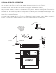
In a head-end system all equipment is located together. There is no backbone copper and all of the horizontal
runs are limited to 100 meters if you are meeting TIA/EIA standards, so passive receivers can be used.
Starting at the camera end, there are several UTPLinks transmitter units available, only one is shown here. This
unit allows the video, power and data to be separated out and fed into standard CCTV cameras.
From the transmitter there is a standard 4 pair Category cable running back to a patch panel up to 100 meters
away for TIA/EIA standards, or 750 feet for standard fixed analog cameras. Distances for analog PTZ cameras must be
determined by the power requirement of the camera. Using 24awg patch cables, connections for each camera are sent to
the CX254 unit. The CX254 unit provides a central point for the combining of the power, data and video signals. Each
camera port is fused and lights on each of the front panel RJ45 jacks show the status of both power and data. Power for
the system is provided by CX254 unit.
Data for the CX254 is routed through the 2 pin jack on the rear of the CX254 unit. In this system CHM22 cards
feed video out the front BNC jacks for connection into standard CCTV equipment. In this example, a DVR is viewed on a
monitor. It could have been a matrix, multiplexer or any other equipment needed for your application.
Patch Panel
CX254
DVR
Monitor
VB43 breaks out
power, video, and data
for connection into
standard CCTV
equipment
22 AWG Cat5e
P/T/Z
Up To
28 WATT
24 AWG Cat5e
four pair
horizontal cabling
NITEK
Power
VB43
Wall Jack
four pair Cat5e
Video
Video
RS422
Power
VB43
Power
VB43
Video