
User guide


INSTALLATION
General Rules
- All horizontal cable runs from a CX254 unit to cameras must be 750 feet or less
- Fixed camera (10 watts or less) wire must be 24awg Cat 5 or better
- All PTZ cameras (10 to 21 watts) must be Cat 5e or better
- All cabling should be T568B wiring
- Always disconnect power to the system while working on the wiring
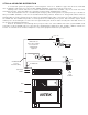
Step 1) Set the POWER Switch and connect the power cord
The CX254 unit can operate on 110VAC or 220VAC but a power selector switch on the rear panel must
be properly set. Please confirm that the rear panel power input selector switch is correct for your
operating voltage. The unit is connected to main power using the IEC320 type C13 power plug on the
rear of the unit. Make sure that you are using a power cord rated for 600 watts or greater.
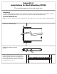
Step 2) Mounting the unit
The CX254 unit can be used as a desk top unit or rack mounted in a standard 19 inch rack. If you are rack
mounting the unit refer to APPENDIX A for rack mounting instructions. Due to the weigh and size, it is
recommended that two persons work together in mounting the CX254 unit in a rack.
Step 3) Mount Cards in Card Cage
The CX254 unit has 5 card slots. When installing a card into the unit use the card guides for alignment.
Use the #4 screw provided on the top to secure the card in place. Do not over tighten the locking screw.
Unused card slots can be covered up with blank covers.
RJ45 jacks on the front of the card provide the connection for each camera run. To meet TIA/EIA
standards your camera runs should be terminated in a patch panel. Using standard patch cables connect the
camera ports to the patch panel. The camera runs should be wired for T568B standard.
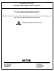
Step 4) Connect Horizontal Runs
Before connecting each camera run to a card verify that it is properly wired, using the CAMERA PORT
wiring chart below. The maximum output of any camera port is 21 watts. The maximum current output for all 4
camera ports on a card is 80 watts total.
Card Slots in front of CX254
Slot 1 Slot 2 Slot 3 Slot 4 Slot 5
CAMERA PORT
8
7
6
5
4
3
2
1
+
-
+
+
-
-
-
+
Power
Power
Power
Data
Data
Power
Video
Video
12345678
568B
2
14
3
Camera Port Wire Chart