
Owners manual

4
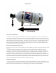
1. Located on the fuel log (injector rail) is a “test port” fitting used by mechanics for checking fuel pressure. This is
usually covered by a black plastic cap and is where the red fuel feed line will be connected. Note: Care should
be taken to be certain the port you have selected is the “Fuel Test-Port”. Many late model cars have several
similar ports that do not contain fuel.
2. Remove the protective cap from the test port fitting. Using a valve core wrench, (valve stem core remover)
remove the inner core from the test port fitting. (Recommend using a proper mechanics shop rag over the fitting
to avoid excess fuel spillage). Check thread compatibility with AN fitting on red stainless fuel line.
(See Illustration D)
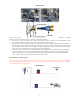
3. If your vehicle does not have a test port then
the
supplied Tee fitting must be spliced into the
factory
fuel
line. The line spliced must be the high-
pres-
sure side (not the fuel return). Choose a
location
between
the fuel filter and the EFI fuel rail, cut
the
hose and insert the Tee using the supplied
clamps,
tighten the
clamps
securely.
ONLY TAP INTO THE HIGH PRESSURE FUEL LINES! DO NOT TAP INTO A
RETURN LINE!
4. Now connect the red fuel line from the fuel supply to the inlet side of the fuel solenoid.
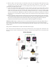
Illustration D
ELECTRICAL HOOK-UP
1. Mount the toggle (Arming) switch in a location that is within easy reach of and in plain sight of the driver.
2. Using 18-ga, blue wire and connectors supplied in the switch kit, connect a HOT lead (12 VDC POSITIVE) to the
“Power” terminal of the toggle switch. (Use 5 amp inline fuse if desired). This power source must be controlled
by the ignition switch (See wiring Schematic).
3. Connect a grounded wire to the “Ground” terminal of the toggle.
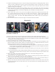
4. The system is furnished with a universal wide-open throttle switch. This WOT micro-switch is designed to work
with the furnished universal mounting bracket. Its maximum capacity is 10 AMPS and should only be used to
activate low amp draw accessories or in conjunction with the supplied relay.
A. Assemble the micro-switch on the mounting bracket using the supplied 3⁄4” 4-40 bolts and nuts. The switch
can be mounted in several different configurations, select the position you require and tighten the bolts. Do
not over-tighten; the plastic micro switch can be damaged.
B. The activation arm on the micro-switch is extra-long. This allows you to twist, bend, or cut it to aid in the
ease of installation.
C. The mounting bracket is made of easily bendable material and may be formed to any configuration that will
allow it to place the WOT switch in the proper location. Be sure the WOT switch is only activated at wide
open throttle.
5. Attach a 18-ga, jumper wire from the remaining terminal “ACC” of the master arming switch to one
of the terminals on the wide open throttle switch.
6. Using the blue 18-ga. wire supplied with the system, connect the remaining wide-open throttle terminal to the
“Red” wire on the supplied heavy duty relay. (See wiring diagram).
7. Use the red 12-ga. wire to connect the “BAT” terminal of the alternator or to the + post on the vehicle battery, to
the “Black” wire on the heavy duty relay. (If desired a 40 amp fuse may be installed here)
8. Attach one wire from each of the Fuel and Nitrous solenoids to the “Green” wire on the relay. Note: These coils
are direct current and it does not matter which wire is used. Now attach the two remaining solenoid wires to a
good ground source.