
Owners manual

5
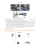
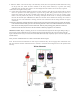
9. Attach the “White” wire from the relay to the fuel safety switch (PN 15118 optional) terminal marked NO. Using
the 18-ga. blue wire, attach the other terminal on the safety switch marked (C) to ground. (See wiring
Schematic) Note: If a fuel safety switch is not used simply attach the “White” wire on the relay to ground.
10. Reconnect the negative battery cable.
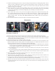
11. At this point both solenoids should be tested for proper operation. Note: (Be sure the nitrous bottle is off and
there is no pressure in the N2O supply line). If you are using a fuel safety pressure switch you must use a
jumper wire between the NO and C terminals when testing the solenoids. To test, turn the “arming” toggle
switch to the ON position and push the “activating” wide-open throttle switch. A clicking sound should be
heard as the solenoids open. IMPORTANT: Make sure that both of the solenoids are clicking! If no sound is
heard or only one of the solenoids is working, check all wire connections and the wiring schematic for proper
connections.
12. With all components mounted and all hose and electrical connections made under the hood connect the feed line
to the nitrous bottle and slowly open the valve listening for leaks. When it is confirmed that there are no nitrous
leaks activate the fuel pump and check for fuel leaks. With the pump running gently break the connection
between the hose from the fuel rail to the fuel solenoid to bleed any trapped air out of this line.
IMPORTANT NOTE: Before continuing, be sure no raw nitrous has been injected into the engine during testing of
the electrical system. If ANY nitrous was accidently injected you must disconnect the coil wire(s) and rotate the
engine with the starter motor for at least 10 seconds with the throttle body completely open to clear the engine of all
residual nitrous.
After you have verified that there is no fuel or nitrous leaks start the engine.
Note: The nitrous and fuel solenoids are rated only for intermittent duty. Do not engage either solenoid for more
than 20 continuous seconds. Solenoids that have “burned or scorched” electro-magnets will not be replaced under
warranty.
Wiring Schematic