
Datasheet

F
Series SK
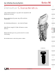
Low & Medium Security Keylocks
www.nkk.com
F13
Indicators
AccessoriesSupplement Tactiles KeylocksRotaries PushbuttonsIlluminated PBSlides Programmable
Touch
Tilt
Toggles
Rockers
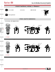
KEY REMOVABLE
Pole &
Throw Model
Key Positions
Pos 1 Pos 2 Pos 3
Connected Terminals
(Terminal numbers are on switch)
Pos 1 Pos 2 Pos 3
Schematic
= Key Removable
= Not Removable
= Maximum Arc
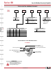
SPDT SK12A ON NONE ON COM-1
____
COM-2
SPDT SK12B ON NONE ON COM-1
____
COM-2
SPDT *SK13D ON OFF ON COM-1 OPEN COM-2
SPDT SK13E ON OFF ON COM-1 OPEN COM-2
Positions 1 & 3
90° Angular Throw
POLES, CIRCUITS & KEY-REMOVABLE POSITIONS
A
12
COM
12
COM
OPE N
POS 1
3
POS 1
3
Zinc Alloy with Chrome Plating (matte finish)
Two keys provided with each switch
(no master key available)
For ordering additional keys:
AT4081 for SK12A and SK12B, marked “1201”
AT4082 for SK13D and SK13E, marked “1301”
Brass with Nickel Plating (shiny finish)
One key provided with each switch
(no master key available)
For ordering additional keys, indicate the same key
number that is engraved on the face of your switch.
Key numbers (001 through 010) randomly assigned.
•
POS 1
2
3
POS 1
2
3
Position 1
90° Angular Throw
B
Positions 1, 2 & 3
45° Angular Throw
D
Position 2
45° Angular Throw
E
* Available with low security only
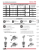
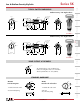
LOCK MECHANISMS & KEYS
Low Security Mechanism
A
Medium Security Mechanism
D
Typical Key Ordering Example:
AT4124-001
(17.0)
.669
(14.2)
.559
(9.4)
.370
(1.8)
.071
(17.0)
.669
(14.2)
.559
(9.4)
.370
(1.8)
.071
(13.7)
.539
(16.2)
.638
(20.0)
.787
(1.8)
.071
AT4082
AT4081