Noke, Inc. 2801 Thanksgiving Way, #220, Lehi UT 84043 Model:DESS1 Installation guide for electric door strike locks March 2018 Overview This document will walk you thru the installation process for our smart locks for doors strikes.
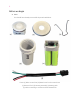
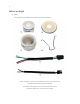
Before we begin A. Parts You should have already received all the parts listed below.
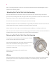
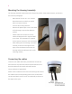
Mounting the Housing Assembly The housing should be mounted onto the desired dry-wall or sheet metal structure, as shown in the overview photograph. - Drill a hole of 57 mm. or 2 ¼ in. into the desired structure on which you would want to mount the device. - Unscrew the housing fastener. - Remove the plastic tape cover on the back of the housing to expose the adhesive surface. - Please make sure the hole to run the cables should point left or right and NOT up or down.
Note: The wiring schematic on how to connect these with the Electric Strike/Magnetic Lock is shown in the following pages. Mounting the Control Unit into the Housing After the cable has been connected, orient the control unit such that the longer and shorter grooves in the Housing mate with the longer and shorter protrusions on the other surface of the control unit. There is only 1 way that these two parts would mate. Press fit the control unit into the housing once oriented correctly.
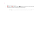
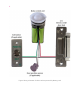
- Black w ire is ground reference. - Red goes to the R ed of the Door strike. B lack from the Door strike connects with ground. - If the Exit button and/or Door position sensor are applicable: Green goes to one terminal of the Exit button and the other terminal is grounded. White goes to one wire of the door sensor and the other wire is grounded.
Figure: Wiring schematic for Door Strikes powered by Battery pack
Noke, Inc. 2801 Thanksgiving Way, #220, Lehi UT 84043 Installation guide for electric door strike locks March 2018 Overview This document will walk you thru the installation process for our smart locks for doors strikes.
2 Before we begin A. Parts You should have already received all the parts listed below.
3 Mounting the Housing Assembly The housing should be mounted onto the desired dry-wall or sheet metal structure, as shown in the overview photograph. - Drill a hole of 57 mm. or 2 ¼ in. into the desired structure on which you would want to mount the device. - Unscrew the housing fastener. - Remove the plastic tape cover on the back of the housing to expose the adhesive surface. - Please make sure the hole to run the cables should point left or right and NOT up or down.
4 - The cable that connects with the strike/magnetic lock and sensors would mate with the black port in the center, with 4 female pins. This cable has 4 wires. - The cable that connects to the power supply has two wires and it mates with the off-center black port with two female pins. The Control Unit should light up once you connect the other end of this cable to a power supply. Blue wire should be ground. Brown wire should be provided between +12 volts to +24 volts.
5 Wiring After mounting the Control Unit into the Housing, please wire the electrical connections before powering the Control Unit. The attached schematic, in the following pages, would provide helpful information. - Blue a nd Brown wires from power cable connect with GND and +12v -to- +24v from the power supply, respectively. - Within the other cable, Black w ire is ground reference. - Red goes to the R ed of the Door strike. B lack from the Door strike connects with grounds.
6 Figure: Wiring schematic for Door Strikes with power supply
FCC Statement This equipment has been tested and found to comply with the limits for a Class B digital device, pursuant to part 15 of the FCC rules. These limits are designed to provide reasonable protection against harmful interference in a residential installation. This equipment generates, uses and can radiate radio frequency energy and, if not installed and used in accordance with the instructions, may cause harmful interference to radio communications.