
Installation Guide
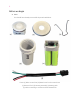

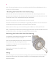

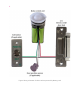
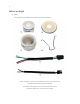
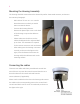
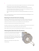
Table Of Contents

4
- The cable that connects with the strike/magnetic lock and sensors would mate with the
black port in the center, with 4 female pins. This cable has 4 wires.
- The cable that connects to the power supply has two wires and it mates with the
off-center black port with two female pins. The Control Unit should light up once you
connect the other end of this cable to a power supply.
Blue wire should be ground. Brown wire should be provided between +12 volts to +24
volts.
Note: The wiring schematic on how to connect these with the Electric Strike/Magnetic Lock is
shown in the following pages.
Mounting the Control Unit into the Housing
After the two cables have been connected, orient the control unit such that the longer and
shorter grooves in the Housing mate with the longer and shorter protrusions on the other
surface of the control unit. There is only 1 way that these two parts would mate.
Press fit the control unit into the housing once oriented correctly.
Now take the metal cover and a small black o-ring carefully and fasten it onto the control unit. It
should mate with the outer threads on the housing. Fasten until tight.
Please make sure the o-ring is not missed during this installation, as it helps seal the unit.
Removing the Control Unit from the Housing
To remove the control unit from the housing, you will
need to use the removal tool which is included.
Insert the terminating ends of the tool into the two
holes in face of the Control Unit, near the grooves on
the circumference of the unit. Once inserted, pull the
tool to remove the Control Unit.
Please refer to the image to the right for better
understanding.