INSTALLATION, OPERATION AND MAINTENANCE MANUAL FOR Blast Chillers/Freezers 1 09/12 Rev.
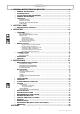
- INDEX 1 GENERAL INSTRUCTIONS ON DELIVERY ……………………………………3 GENERAL INSTRUCTIONS ……………………………………………………………………3 TECHNICAL DATA ………………………………………………………………………………3 LIST OF REGULATION REFERENCES ……………………………………………………3 GENERAL INSTRUCTIONS ……………………………………………………………………3 SETTING UP ………………………………………………………………………………………4 MACHINE LOADING …………………………………………………………………………………………………5 POSITION OF TRAYS ………………………………………………………………………………………………5 STORAGE TIME AND TEMPERATURE …………………………………………………………………………5 CORE PROBE ……………………………………………
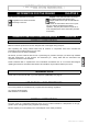
- OPERATION MANUAL INFORMATION FOR THE READER This manual is subdivided into two parts. CHAPTER 0 2nd part: covers all the information necessary to the qualified operators authorized to move, transport, install, service, repair and demolish the appliance. While users are instructed to refer to the 1st part only, the 2nd part is addressed to skilled operators. They may also read the 1st part for a more complete picture of the information provided if necessary.
- OPERATION MANUAL SETTING UP Before setting to operation thoroughly clean the cooling cabinet with a suitable detergent or sodium bycarb dissolved in lukewarm water. Clean the appliance inside to remove any condensate caused by the Manufacturer's final testing.
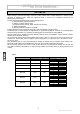
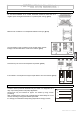
- OPERATION MANUAL MACHINE LOADING Do not stack foodstuffs to be cooled. Thickness should be lower than 2” in negative quick cooling and lower than 3” in positive quick cooling. (pict.1) Pict.1 Make sure air circulation is not hampered between food trays. (pict.2) 0,19”-0,79” Pict.2 The grid-holding frame (included in those models which include trolleys) is to be located at the center of the cabinet. (pict.3) Pict.3 POSITION OF TRAYS Place the trays as close to the evaporator as possible. (pict.
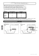
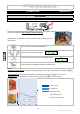
- OPERATION MANUAL Table 3 shows the storing time rates for a few examples of frozen food. Do not leave cooked products at room temperature before quick cooling, as this may allow the loss of moisture, which will affect food freshness. The cooled product should be wrapped in a specific film for foodstuffs (better still, vacuum stored) and provided with a sticker reporting the content [A], date of processing [B] and expiration date [C] written in permanent type ink (pict.6). Tab.
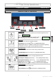
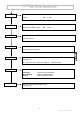
- OPERATION MANUAL CONTROL PANEL CHAPTER 2 DESCRIPTION OF CONTROLS ON/OFF KEY START/STOP KEY UP KEY ENTER KEY MENU/ESC KEY DOWN KEY ON/OFF key Pressing the key for 5 sec the controller turns off and the sign blinks on the display OFF _ When this button is pressed the controller lights up again, preparing itself to start an IFR chilling cycle. IFR Esc Enter key Allows access to a menu or parameter selection. Manual defrost: press the key During a cycle: press the the ongoing cycle.
- OPERATION MANUAL Programs Program selection IFR: Automatic quick cooling program Values setting not required. Can be activated with core probe only. With the IFR program, there is no freezing on foodstuffs outer surface. (no risk of third-degree freezing). The IFR program must not be used in negative quick cooling cycles.
- OPERATION MANUAL Defrost Defrost start Select Print Ok No Menu for printing memorized quick cooling cycles With printer available, select: Clock Setting or Ok or No Clock setting Set date and time Language Set language Select the desired language Alarm Menu for displaying the alarms. (reading only) S = alarm start, E = alarm stop, Service = customer service Service Appliance basic setting. Set password “-19”.
- OPERATION MANUAL OPERATION CHAPTER 3 PROGRAMS IFR CHILLING CYCLE The IFR is an innovative patented system of positive quick cooling which allows the cycle optimization for each type of foodstuffs by preventing superficial freezing. Temperatures are detected by a three-sensor needle probe (ref. page 6, “Core probe”). Press menu/esc to select the desired menu Use the keys up and down to display Programs Esc Press enter to confirm your choice.
- OPERATION MANUAL RECOMMENDED WORKING CYCLES Recommended working cycles are pre-programmed. Parameters cannot be changed. Press menu/esc to select the desired menu Programs Use the keys up and down to display Esc Press enter to confirm your choice.
- OPERATION MANUAL Press enter to confirm your choice. The display shows IFR Esc Use the keys up and down to display User Esc 01 NAME Press enter to confirm your choice. The display shows (example) Esc Use the keys up and down to scroll all the saved programs Press start/stop to immediately activate the selected cycle STORING USER’S PROGRAMS It is possible to save up to 20 USER programs.
- OPERATION MANUAL DELETE A USER’S PROGRAM Press menu/esc to select the desired menu Use the keys up and down to display Programs Esc Press enter to confirm your choice. The display shows IFR Esc Use the keys up and down to display User Esc Press enter to confirm your choice. The display shows 01 NAME Esc Use the keys up and down to scroll all the saved programs Keep menu/esc pressed for 5 seconds.
- OPERATION MANUAL Keep menu/esc pressed for 5 seconds. The display shows Press up. The display shows Cancel progr Ok No Rename progr Ok No A _ _ _ _ _ _ Press enter. The display shows Esc Type in the name of the program which is to be memorized using buttons scroll through the letters and numbers, and press next character.
- OPERATION MANUAL MANUAL CYCLES NEGATIVE FREEZING CYCLE WITH CORE PROBE: cycle suitable for freezing foodstuffs using a room temperature of about -22[°F]. The cycle is controlled by the core probe. WITH TIMER: cycle suitable for freezing foodstuffs using a room temperature of about -22[°F]. The cycle is time-controlled. SOFT POSITIVE CHILLING CYCLE WITH CORE PROBE: cycle suitable for cooling foodstuffs with thickness lower than 1.5” using a room temperature of about +32[°F].
- OPERATION MANUAL NEGATIVE FREEZING CYCLE WITH CORE PROBE Press menu/esc to select the desired menu Manual Use the keys up and down to display Esc Press enter to confirm your choice. Press up to display Ok Negative Esc No Press enter to confirm your choice. Press up to display Neg Core Ok Esc No Press enter to confirm your choice. The display shows Use buttons Neg Core to modify the set point value of the temperature in the room Speed Press enter to confirm your choice.
- OPERATION MANUAL Press up to display Neg Time Ok Esc No Press enter to confirm your choice. The display shows Use buttons Neg Time 90’ Esc to modify the duration of the cycle. Speed Press enter to confirm your choice. The display shows Use buttons 100% Esc to modify fan speed Press enter to confirm your choice.
- OPERATION MANUAL SOFT POSITIVE CHILLING CYCLE WITH TIMER Press menu/esc to select the desired menu Manual Use the keys up and down to display Esc Press enter to confirm your choice. Press up to display Positive Soft Ok Esc No Press enter to confirm your choice. Press up to display Soft Time Ok Esc No Press enter to confirm your choice. The display shows Use buttons Soft Time to modify the duration of the cycle. Speed Press enter to confirm your choice.
- OPERATION MANUAL Press up to display Hard Core Ok Esc No Press enter to confirm your choice. The display shows Use buttons Hard Core to modify the set point value of the temperature in the room Speed Press enter to confirm your choice. The display shows Use buttons -13°F Esc 100% Esc to modify fan speed Press enter to confirm your choice.
- OPERATION MANUAL STORING CYCLES POSITIVE STORE Press menu/esc to select the desired menu Store Use the keys up and down to display Esc Press enter to confirm your choice. Press up to display Positive Ok No Set Point Press enter to confirm your choice. The display shows Use buttons to modify the set point value of the temperature in the room. Press enter to confirm your choice. The display shows Use buttons 36°F Esc Speed 50% Esc to modify fan speed.
- OPERATION MANUAL Press enter to confirm your choice. The display shows Use buttons Speed 50% Esc to modify fan speed. Store Press enter to confirm your choice. The display shows Esc Press the start/stop key to immediately start the storing cycle DEFROSTING Press menu/esc to select the desired menu Use the keys up and down to display Defrost Esc Press enter to gain access to the defrost activation The display shows Start? Ok No Press enter to immediately activate the defrosting cycle.
- OPERATION MANUAL Press enter to start printing the saved cycles (quick cooler name, date, number of program being used, name of program being used, temperature set point and quick cooling type, starting time and room/core temperature, end-ofcycle time and room/core temperature) 22 09/12 Rev.
- OPERATION MANUAL MAINTENANCE CHAPTER 4 MAINTENANCE AND CLEANING CLEANING THE CABINET Clean inside the cooling cabinet daily. Both the cabinet and all the internal components have been designed and shaped to allow washing and cleaning all parts easily. Before cleaning, defrost the appliance and remove the internal drain. Disconnect the master switch. Clean all components (stainless-steel, plastic or painted parts) with lukewarm water and detergent.
- OPERATION MANUAL Wash the door gasket with water. Accurately dry with a dry cloth. We recommend wearing protecting gloves throughout the operations. (pict.13) Pict.13 Hand-wash the probe using lukewarm water and a mild detergent or products with biodegradability higher than 90%. Rinse with water and sanitary solution. Do not use detergents containing solvents (such as trichloroethylene, etc) or abrasive powders ATTENTION: do not use hot water to wash the probe (pict.14) Pict.
- OPERATION MANUAL DISCONTINUED USE Should the machine be disconnected over long periods, follow the instructions below to maintain the appliance in good condition: Pict.18 OFF Turn the main switch OFF. (pict.18) Pict.19 Disconnect the plug. (pict.19) Empty the appliance and clean it in accordance with the instructions given in the chapter "CLEANING". Leave the door ajar to prevent a bad smell. Cover the compressor unit with a nylon cloth to protect it from dust. (pict.20) Pict.
- INSTALLATION MANUAL INSTALLATION INTRODUCTION After unpacking the appliance make sure it has not been damaged. (pict.21) Make sure the supply wiring comply with the ratings (i.e., V, kW, Hz, no. of phases and main power). All inter-wiring between the electrical panel and the unit must be done in accordance with the national electric code and all state and local codes. Check and record the coolant type inside the refrigeration system and refer to this recorded data upon any refrigerant refill. Pict.
- INSTALLATION MANUAL Pict.25 Do not place the refrigerated compartment near heat sources. (pict.25) Pict.26 Remove pvc protective film from all over the appliance. (pict.26) Place the appliance onto the required working site. (pict.27) Avoid locations with exposure to direct sunlight. Do not place the appliance in hot, poorly-ventilated rooms. Pict.27 Pict.28a Mod. BCF44244 / BCB44244 / BC40-4 / BCF93558 / BC80-8 / BCF11514 / BC113-14 Leave a min.
- INSTALLATION MANUAL WIRING The connection to power supply may be carried out at the back of the appliance after removing the protection grid. (pict.31) Pict.31 CONNECTION TO CONDENSATE DRAIN Pict.36 On certain models, a condensation discharge 1.2” diameter hose installation is necessary, ("SAREL" or any similar type). The current general and local regulations pertaining to drains are to be complied with. (pict.
- INSTALLATION MANUAL CLOCK SETTING Press menu/esc to select the desired menu Use the keys up and down to display Clock Setting Esc Press enter to gain access to the clock setting mode The display shows Date: Hour: 06/11/05 14:22:46 Use the keys up and down to change the flashing digit Press enter to confirm and pass to the next value Press menu/esc to exit LANGUAGE Press menu/esc to select the desired menu Use the keys up and down to display Language Esc Press enter to display the first languag
- INSTALLATION MANUAL ALARMS AND FAULT ANALYSIS (TAB.5) Press menu/esc to select the desired menu Alarm Use the keys up and down to display Esc Press enter to gain access to the mode for displaying alarms No Data If there are no alarms saved, the display shows Esc If there are alarms saved, the display shows the last alarm starting time as well as the A05 Insert probe progressive number ranging from A01 to A30 S 14:21 15/12/03 Press enter to get further information about the alarm. The max. or min.
- INSTALLATION MANUAL TAB.
- INSTALLATION MANUAL SERVICE PARAMETERS DESCRIPTION OF PARAMETERS Parameter P01 P02 P03 P04 P05 P06 P07 N01 N02 N03 N04 A01 A02 A03 A04 A05 A06 A07 A08 D01 D02 D03 D04 D05 D06 S01 S02 S03 S04 S05 S06 S07 S08 S09 S10 Description POSITIVE QUICK COOLING Room SetPoint in pos. quick cooling, Soft phase SetPoint in pos. quick cooling, Hard Needle SetPoint in pos.
- INSTALLATION MANUAL Parameter C01 C02 C03 C04 C05 C06 C07 C08 C09 C10 C11 C12 R01 R02 R03 R04 R05 R06 R07 R08 R09 R10 R11 R12 R13 F01 F02 F03 F04 F05 F06 F07 F08 F09 F10 F11 PR1 CF1 CF2 Description CONFIGURATION Door input (0 de-activated; 1 activated) Door open polarity Door open alarm delay Activates buzzer (0 de-activated; 1 activated) Buzzer duration at the end of quick cooling cycle Temperature difference in the first phase of needle insertion test (0 = test excluded) Duration of the second phase o
- INSTALLATION MANUAL Parameter B01 B02 B03 B04 B05 B06 B07 B09 B10 B11 B12 B13 B16 B17 B18 B19 B20 B21 B22 B23 B24 B26 B27 B28 ADD SC MB1 MB2 G01 Description I.F.R. Room thermostating temperature in the first phase Under surface T control start temperature First coefficient of the control relation Second coefficient of the control relation Third coefficient of the control relation Under surface T initial value determining the end of the first phase Phase two formula coefficient Under surface t min.
- INSTALLATION MANUAL Use the keys up and down to select the password “-19” Press enter to confirm your choice.
- INSTALLATION MANUAL Press enter to gain access to the mode for cancelling the data stored in the memory Reset Memory? Ok No The display shows Press Enter to erase the saved data Press menu/esc to exit RESTORING DEFAULT PARAMETERS This function restores the original parameters. ATTENTION: should you use the device with the “RESTORE” option, available on the card, please contact the manufacturer for proper setting of the electronic controller configuration parameters.
- INSTALLATION MANUAL INPUTS/OUTPUTS Press menu/esc to select the desired menu Inputs/Outputs Use the keys up and down to display Esc Press enter to gain access to the mode for displaying inputs and outputs Room Probe The display shows 21°F 59°F Use the keys up and down to scroll the data to display Room Probe 21°F 59°F Room: Room air temperature Probe: Core temperature – see core probe section Food External 93°F 90°F Food: under surface probe – see core probe section External: over surface probe
- INSTALLATION MANUAL ELECTRICAL COMPARTMENT ACCESS The following operations are to be carried out by skilled staff only. Pict.38 OFF Turn the main switch OFF. (pict.38) Pict.39 Disconnect the plug. (pict.39) Pict.40 To be able to access the electrical compartment: Mod. BCF44244 / BCB44244 / BC40-4 Remove the front panel (pict.40) with a tool and move the electric board box (pict.41) along the slides Pict.41 Remove the electrical compartment cover with a tool to access the internal components.
- INSTALLATION MANUAL Pict.45 Two delayed fuses are inserted in the power supply line; extract the blown fuse and replace it with a fuse having the same characteristics. (pict.45) WIRING DIAGRAM PLATE The diagram is shown on pict.47, see page 46.
- INSTALLATION MANUAL The improper disposal of Waste Electrical and Electronic Equipment is liable to punishment under the relevant laws in the countries where the offence is committed. Waste electrical and Electronic Equipment may contain hazardous substances with potential harmful effects on the environment and human health. You are urged to dispose of them properly. DOOR REVERSAL Blast Chillers are normally supplied with a right opening door.
- INSTALLATION MANUAL Ingestion: it can cause vomit.. If conscious, rinse mouth with water and drink 200-300 ml of water. Seek medical attention. Other medical treatment: symptomatic treatment and support therapy when indicated. Do not administer adrenaline or sympathetic mimetic drugs after exposure, due to the risk of arrhythmia and possible cardiac arrest. 4) Environmental data Persistence and degradation HFC 143a: slow decomposition in lower atmosphere (troposphere).
- INSTALLATION MANUAL DIMENSIONS Please refer to the dimensions of your own appliance.
- INSTALLATION MANUAL BCF22020 39-5/8” 40-15/16” Ø1-3/16” 33-1/8” 2-5/16” 36-3/16” 5-15/16” 73-5/8” 33” 20-9/10” 42-11/16” 34-9/20” Ø1-3/16” 7-13/16” 22-5/8” 2-5/16” 2-5/16” 16-15/16” 32-1/16” 5-1/8” 77-15/16” 39-5/8” 40-15/16” 43 09/12 Rev.
- INSTALLATION MANUAL APPENDIX TAB.1a Model Gross weight [lb] Net weight [lb] Dimensions Capacity Mass /cycle [lb] Internal volume [cu.ft.
- INSTALLATION MANUAL TAB.4 Minimum air circulation through condenser coil Air qty [cfm] Model BCF44244 BCB44244 BC40-4 BCF93558 BC80-8 BCF11514 BC113-14 BCF22020 650 2060 2530 5300 45 09/12 Rev.
- INSTALLATION MANUAL Pict.