Quality Refrigeration Since 1947 Walk-In InstallatIon Manual for: kold locker™ fast trak® fInelIne™ MInI rooMs envIro-lIne Nor-Lake, Inc. Registered to ISO 9001:2008 File No. 10001816 © 2013 Nor-Lake, Inc 07/13 Rev.
The Quality Systems at Nor-Lake, Incorporated have been registered by UL to ISO 9001:2008. Your Nor-Lake Walk-In Cooler (Freezer) was quality engineered and produced under rigid factory controls. It features the very latest in manufacturing technology plus innovative design techniques that will provide the ultimate in user convenience. Please maintain this service-reference material in a handy file for an immediate answer to any questions you may have concerning your Nor-Lake Walk-In.
PROdUCT SAfETy POLICy Of NOR-LAKE, INC. We strive to provide those who buy and/or use our product with equipment which is: 1. Developed by applying professional engineering principles in product research, development and user safety. 2. Designed to comply with or exceed industry performance and safety regulations. 3. Thoroughly reviewed and professionally tested for function, reliability and product safety. 4.
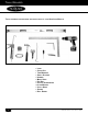
Tools RequiRed tools requIred for uncratIng and InstallatIon of your • • • • • • • • • • • • 2 nor-lake Walk-In LeveL CauLk Gun Tape Measure safeTy GLasses HaMMer MeTaL snips pry Bar pHiLLips sCrewdriver aLLen wrenCH uTiLiTy knife square driLL driver © 2013 Nor-Lake, Inc 07/13 Rev.
Walk-in insTallaTion GeneRal infoRmaTion WALK-IN INSTALLATION General Information This walk-in cooler or freezer was produced utilizing the latest in manufacturing technology, the highest quality materials available, along with innovations that make it a distinctive product in its field. Despite rigid controls in the production of the product, there is no substitute for thoroughly reading and UNDERSTANDING the instructions that follow. The result will be an orderly and efficient installation.
Walk-in insTallaTion GeneRal infoRmaTion Packing List • Locate packing list and use as reference during uncrating. • Remove protective packaging and locate hardware bag. The hardware bag also contains accessory parts for this walkin together with an erection diagram, a layout of the screed assembly for floorless walk-ins, and a detailed packing list of all parts furnished for this individual walk-in. All parts should be compared to the packing list.
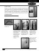
foam Panel sToRaGe fOAM PANEL STORAGE If foam walk-in panels require storage at the job site prior to installation, the following steps must be taken to protect the panels against both staining from moisture and sunlight, and denting by workers and traffic. Whenever possible, the panels should be stored indoors, and should remain in the crating pallet they were originally shipped in.
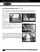
eRecTion diaGRam ERECTION dIAGRAM The erection diagram, as furnished with each walk-in, is a detailed plan that illustrates the placement of every wall, corner, ceiling and floor panel that comprises a complete, individual walk-in. The erection diagram for all installations clearly shows the direction of the male and female formed profile of every wall panel and every corner panel.
secTion laTches SECTION LATCHES All wall, corner, ceiling and floor panels are joined and locked together by the mechanical action of section latches which are integrally foamed into the panels near the perimeter edges. A section latch consists of two halves – a lock housing which contains a cam actuated locking arm, or hook, and a strike housing which contains the engagement pin. Both housing halves are securely anchored in the foam core of the panel.
Walk-in insTallaTion - siTe selecTion, Base PRePaRaTion SITE SELECTION, BASE PREPARATION & LEvELING THE fLOOR WALK-IN COOLER OR fREEZER WITH A fLOOR One of the most important considerations in the erection of a walk-in cooler or freezer is the building floor or the surface upon which the walk-in will rest. As with any structure, a firm and level foundation is essential to achieve a perfect end result.
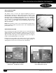
flooR insTallaTion (shim levelinG meThod) fLOOR INSTALLATION (Shim Leveling Method) for walk-ins subject to light to moderate loads Locate the highest point within the perimeter lines. A transit or surveyor’s level or rotary laser level is an ideal instrument to use for locating this point. When the highest point is located, mark it directly on the floor and refer to the erection diagram to determine where the high point is located with respect to the walkin floor plan.
flooR insTallaTion (shim levelinG meThod) Place the second panel in position next to the first floor panel but dO NOT LOCK! Shim the second panel, where necessary, using the same procedure as was used on the first panel. When all four edges of the second floor panel are properly shimmed, lock the two panels securely together.
Walk-in insTallaTion - siTe selecTion, Base PRePaRaTion SITE SELECTION, BASE PREPARATION WALK-IN COOLER WITHOUT A fLOOR INSTALLEd ON 1” vINyL SCREEd IMPORTANT! Do not attempt to erect a floorless walk-in FREEZER on a existing building floor that has not been specially prepared and adequately insulated for below freezing storage temperatures.
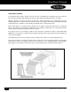
Walk-in insTallaTion - siTe selecTion, Base PRePaRaTion Note: All sealers lettered alike are interchangeable. 8’-1 1/2’’ OVERALL SCREED WIDTH THAT CONTACTS THE FLOOR IS 5 1/2’’ EXISTING WALL EXISTING WALL 2’’ MINIMUM 5 1/2’’ Sealers may also be numbered by part number EXACT DIMENSIONS OF SCREED ASSEMBLY (REFER TO SCREED DIAGRAM) (Screed Diagram) HIGHEST POINT (EXAMPLE ONLY) HIGHEST POINT (EXAMPLE ONLY) 2’’ MINIMUM 39 1/2’’ Note: Corners are shipped in two pieces.
Walk-in insTallaTion - siTe selecTion, Base PRePaRaTion When the entire screed assembly is leveled and supported by shimming, as required, CAREFULLY AND WITHOUT DISTURBING THE SHIMMING MATERIAL, lift the screed sections, tip them upside-down and apply a heavy bead of construction sealant to the bottom of the screed section along both of the edges that contact the building floor surface.
Walk-in insTallaTion - siTe selecTion, Base PRePaRaTion TAPE z SHIMMING MATERIAL SEALANT Figure 5 ALTERNATE SHIMMING METHOd fOR 1’’ vINyL SCREEd If the surface that the vinyl screed will occupy is level, except for an occasional low point, the screed may be secured directly to the building floor and compensation for the low points may be achieved by shimming the support shoulders on the inside of the screed.
Walk-in insTallaTion - siTe selecTion, Base PRePaRaTion SITE SELECTION, BASE PREPARATION WALK-IN COOLER OR fREEZER WITHOUT A fLOOR INSTALLEd ON fOAMEd SEALERS IMPORTANT! Do not attempt to erect a floorless walk-in FREEZER on an existing building floor that has not been specially prepared and adequately insulated for below freezing storage temperatures.
Walk-in insTallaTion - siTe selecTion, Base PRePaRaTion 2” MINIMUM 2” MINIMUM Figure 2 2” MINIMUM 2” MINIMUM Figure figure 3 3 One of the most important procedures that will be encountered in the base preparation is LEVELING THE SEALER (SCREED). It must be PERFECTLY LEVEL! If it is not, the wall panels will follow the irregularities of the building floor which will directly affect subsequent procedures such as panel latching, panel gasket seal, ceiling panel assembly and other.
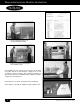
Walk-in insTallaTion - siTe selecTion, Base PRePaRaTion SEALER GUIdE INSTALLATION Locate the SEALER GUIDES. They are bundled together and packed along with the walk-in corner or wall panels and are labeled accordingly. Sealer guides are strips of 3/8” plywood 2 1/4” wide as shown in Figure 1. Refer to the SEALER GUIDE DIAGRAM. Select the proper sealer guides and position them as shown by the circled letters on the diagram.
Walk-in insTallaTion - siTe selecTion, Base PRePaRaTion figure 5 After the first sealer (screed) section is positioned over the sealer guide and over the highest point, it must be LEVELED PERFECTLY not only over its length but, across its width, as well. to achieve this, shimming material will probably be required. Vinyl floor tile cut in strips 7/8” wide by 6” long make ideal shimming strips that can be placed beneath the sealer, wherever necessary, to achieve levelness.
Walk-in insTallaTion -Wall & ceilinG Panel eRecTion WALK-IN INSTALLATION Wall & Ceiling Panel Erection The installation instructions that follow apply to any walk-in cooler or freezer where the wall panels are supported either by foamed walk-in floor panels or by a floor sealer (screed) assembly which has been accurately located and properly leveled. NOTE: The procedure for erecting wall and ceiling panels will be identical in all cases.
Walk-in insTallaTion -Wall & ceilinG Panel eRecTion If the first corner panel is supported by a 1" vinyl sealer (screed), seek assistance to support the corner panel in a vertical position until succeeding wall panels are installed. Wall and corner panels do not lock to the vinyl sealer (screed). Select the next panel as indicated on the floor plan and position it on the floor or sealer (screed) close enough to the first panel installed so that section latch engagement is possible.
Walk-in insTallaTion -Wall & ceilinG Panel eRecTion As each wall panel or corner panel is erected and locked in an adjoining panel along the vertical joint, engage the section latches to the floor panels by turning the hex locking wrench ONLY ABOUT 1/4 TURN CLOCKWISE. Make certain that the wall or corner panel is perfectly aligned with the floor panel or foamed sealer before engaging the section latches.
Walk-in insTallaTion -dooR/dooR secTion dOOR/dOOR SECTION A standard door/door section consists basically of a single wall panel that contains an entrance door and several accessories. The electrical components contained in this panel were prewired at the factory. They include the anti-condensate door opening heater, the pilot light, and switch and a vapor proof interior light.
Walk-in insTallaTion -dooR/dooR secTion NOTE: If, for some reason, conditions on the site prohibit the installation of the walls and ceilings in the recommended order, install the wall and ceiling panels in a logical sequence that will permit accessibility for installation of the last panel. Remember to schedule ceiling panel installation at the proper intervals to serve as supporting ties between installed wall panels.
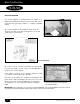
Walk-in insTallaTion -dooR/dooR secTion W ALK -I N I NSTALLATION -D OOR /D OOR S ECTION IMPORTANT! APPLY SEALANT UNDER THRESHOLD MAKE SURE THAT THE DOOR/DOOR SECTION IS PERFECTLY PLUMB BEFORE ATTACHING THE SLAM BRACES TO THE FLOOR. Fig. 11 Note: Add sealant between threshold and floor to seal. Apply Sealant Under Threshold Fig.
Walk-in insTallaTion - siTe selecTion, Base PRePaRaTion Fig. 13 SEALING THE JUNCTURE Of WALLS TO BUILdING fLOOR Apply a generous amount of NSF approved sealant to achieve a vapor seal between the bottom edge of all wall, corner, door and partition panels and the building floor. The sealant must be applied to both inner and outer edges of all perimeter walls and to both edges of partition walls where they meet the building floor.
exTeRioR RamP insTallaTion insTRucTions Exterior Ramp Installation Instructions Center ramp in front of door opening. Then using the 1-1/2” x 1-1/2” x 3-1/2” angle the screws provided, attach the ramp to the walk-in, as in the illustration below. 26 © 2013 Nor-Lake, Inc 07/13 Rev.
inTeRioR RamP insTallaTion insTRucTions Interior Ramp Installation Instructions Step 1 Step 2 After floor sections are in place and fully locked together, apply approximately 1/8” bead of sealant to the interior metal, 3/8” in from the ramp cut out. Also apply approximately 1/8” bead of sealant to the center of the exterior metal lip.
Walk-in insTallaTion-elecTRical connecTions WALK-IN INSTALLATION Electrical Connections WALK-IN COOLER OR FREEZER WITH A SINGLE INTERIOR LIGHT MOUNTED ON THE DOOR SECTION CAUTION: ELECTRICAL CONNECTIONS TO THE WALK-IN MUST COMPLY WITH APPLICABLE PORTIONS OF THE NATIONAL ELECTRICAL CODE AND ANY OTHER ELECTRICAL CODES THAT MAY HAVE JURISDICTION OVER THE INSTALLATION! A dedicated electrical power supply circuit for the walk-in is recommended.
Walk-in insTallaTion-elecTRical connecTions IMPORTANT! When all field wired connections are completed in the junction box located on top of the ceiling section, be sure to THOROUGHLY SEAL the conduit fitting through which the wiring projects into the junction box. The silicone sealant provided is well suited for this purpose. Failure to do so will permit moisture to form within the junction box and electrical fixture(s) and potentially cause a short.
Walk-in mainTenance AdJUSTABLE HINGE Nor-Lake 26”, 30”, & 36” wide walk-in doors are provided with an adjustable hinge. The adjustable hinge provides the ability to square a door within the door jamb. If a door requires adjustment: Open the door and you will find a small chrome plug button, on the edge of the door behind the upper hinge. Before any adjustment you must first slightly loosen the screws on the hinge strap on the door. Then pop off the chrome plug button.
Walk-in mainTenance dOOR GASKET REPLACEMENT 1. Place the door, exterior face down, gasket up, on a clean, smooth surface that will not mar or scratch the finish. 2. The magnetic door gasket consists of a cavity containing the magnetic strip, a bellows cavity that permits the gasket to conform to irregular surfaces, and a base section that features a dart- shaped projection that serves as the attachment means when it is forced into the slot in the door breaker. 3.
Walk-in mainTenance Sweep GaSket Replacement 1. Determine which sweep gasket your walk-in has: a. Old sweep gasket held in with screws (go to #2) b. New style held in by integral dart (go to #5 and skip #6). 2. Remove screws that retain the old style gasket (if no screws hold in gasket, skip to #5) and remove gasket. 3. With old sweep gasket removed, determine if door gasket length needs to be cut to accommodate new style door sweep by placing sweep gasket into position.
Walk-in mainTenance dOOR CLOSER The door closer was factory-installed and tested for proper operation before shipment. This small, but powerful device provides smooth and positive closing with only a minimum of attention. No lubrication Correct with Door Closed of any kind is required. It is recommended that, at least once each month, the relationship of the hook and roller to each other be examined.
Walk-in mainTenance ANTI-CONdENSATE dOOR OPENING HEATER To prevent condensate from forming around the outer edges of the door opening, an anti-condensate heater has been installed around the perimeter of the door opening. This constant-energy, low wattage, electric heater wire elevates the temperature of the door jambs and threshold sufficiently to maintain these surfaces above the dewpoint temperature of the surrounding air preventing condensation.
Walk-in mainTenance Again, MAKE SURE THAT THE POWER IS DISCONNECTED and remove the cover plate from the pilot light and switch on the front of the door section. Remove the two screws that attach the pilot light and switch assembly to the switch box and pull the pilot light and switch assembly out of the switch box enough to expose the terminal screws on the device.
Walk-in mainTenance Using small pieces of electrical tape, fasten the heater wire in place. Lift the heater wire at each corner and apply three thicknesses of electrical tape around the insulation over a length of approximately 3". Follow by forming a small loop at each corner to permit expansion and contraction of the heater wire without strain at these points. After the loops are formed, tape them in place with a short strip of electrical tape.
Walk-in mainTenance ELECTRICAL CONNECTION Referring to the wiring diagram in the "Electrical Connections" section of this manual, connect the heater wire leads as shown. If short lengths of the lead wires were left as indicators, connect the replacement heater leads to those points of connection and discard the short indicator lengths. NOTE: If one of the heater leads connects to another wire through a wire connector, obtain a properly sized, twiston wire connector for this purpose.
final Checklist for Installation of Nor-Lake, Inc. Walk-in and Refrigeration Location# Sales Order # dear Refrigeration Contractor: Our goal is to supply our customers with the best equipment available. This is accomplished by combining the highest quality commercial refrigeration equipment with a craftsman like installation that meets all factory requirements. This document will help you understand and verify the installation meets these requirements.
11. Are the lights installed, connected to the light switch and operating correctly? 12. Have all electrical and other penetrations been properly sealed as recommended by Nor-Lake? 13. Is the temperature sensor extended away from door and mounted on the wall? 14. Is the strip curtain mounted in place and secured? 15. Are the refrigerant piping and electrical cable supported and strain free? 16. Is the serial tag correctly installed? 17.
Nor-Lake, Incorporated 727 Second Street P.O. Box 248 Hudson, Wisconsin 54016 40 800-955-5253 Foodservice Sales 800-477-5253 Scientific Sales 800-388-5253 Parts/Service 715-386-2323 715-386-6149 FAX Email: service@norlake.com www.norlake.com © 2013 Nor-Lake, Inc 07/13 Rev.
Refrigeración de calidad desde 1947 Manual de InstalacIón de cáMara frIgorífIca para: kold locker™ fast trak® fInelIne™ MInI rooMs envIro-lIne Nor-Lake, Inc. Registered to ISO 9001:2008 File No. 10001816 © 2013 Nor-Lake, Inc 07/13 Rev.
Los Sistemas de calidad de Nor-Lake, Incorporated han sido registrados por UL a ISO 9001:2008. Su Cámara frigorífica (congeladora) Nor-Lake tiene un diseño de calidad y fue fabricada bajo rígidos controles de producción. Cuenta con la más avanzada tecnología de fabricación y técnicas de diseño innovadoras que proporcionan máxima conveniencia para el usuario.
PóLIZA dE SEGURIdAd dEL PROdUCTO dE NOR-LAKE, INC. Nos esforzamos para proveer a quienes compran o usan nuestros productos equipos que son: 1. Desarrollados aplicando los principios de ingeniería de investigación de productos, desarrollo y seguridad del usuario. 2. Diseñados para cumplir o aún exceder los estándares de rendimiento y las reglas de seguridad de la industria. 3. Revisados minuciosamente y probados profesionalmente para comprobar la función, confiabilidad y seguridad del producto. 4.
heRRamienTas HerraMienTas necesaRias neCesarias para deseMBaLar y MonTar su • • • • • • • • • • • • 4 CáMara friGorífiCa nor-Lake niveL pisToLa de CaLafaTeo CinTa MéTriCa Gafas de seGuridad MarTiLLo Tijeras para CorTar MeTaL paLanqueTa desTorniLLador pHiLLips LLave aLLen CuCHiLLo para uso GeneraL esCuadra TaLadro © 2013 Nor-Lake, Inc 07/13 Rev.
infoRmación GeneRal de insTalación de la cámaRa fRiGoRífica INSTALACIóN dE LA CÁMARA fRIGORÍfICA Información general Esta cámara frigorífica o congeladora fue producida utilizando lo último en tecnología de fabricación, los materiales de más alta calidad disponibles, junto con innovaciones que la hacen un producto destacado en su campo. A pesar de los rígidos controles en la producción del producto, se debe leer cuidadosamente y COMPRENDER las instrucciones que siguen.
infoRmación GeneRal de insTalación de la cámaRa fRiGoRífica Lista de empaque • Busque la lista de empaque y úsela como referencia durante el desempaque. • Quite el empaquetado protector y localice el saco con artículos de ferretería.
almacenaje del Panel de PlásTico esPonjoso ALMACENAJE dEL PANEL dE PLÁSTICO ESPONJOSO Si los paneles de espuma de la cámara necesitan ser almacenados en el sitio de trabajo antes de la instalación, debe seguir los siguientes pasos para proteger los paneles, tanto contra las manchas de humedad como contra la luz del sol y de abolladuras causadas por los trabajadores o el tránsito.
diaGRama de monTaje dIAGRAMA dE MONTAJE El diagrama de montaje, según se provee con cada cámara, es un plan detallado que ilustra la ubicación de todos los paneles de pared, esquina, techo y piso que componen cada cámara completa. El diagrama de montaje de todas las instalaciones muestra claramente la dirección de los perfiles machos y hembras de cada panel de pared y cada pared de esquina.
ceRRojos de sección CERROJOS dE SECCIóN Todos los paneles de pared, esquina, techo y piso se unen y se traban por la acción mecánica de los cerrojos de sección que están enteramente cubiertos de plástico esponjoso dentro de los paneles cerca de los bordes perimetrales. Un cerrojo de sección consta de dos mitades: el alojamiento del cerrojo, que contiene un brazo bloqueador o gancho accionado por una leva, y un alojamiento de cerradura hembra que contiene la clavija de enganche.
insTalación de la cámaRa fRiGoRífica - selección del siTio y PRePaRación de la Base SELECCIóN dEL SITIO, PREPARACIóN dE LA BASE y NIvELACIóN dEL PISO CÁMARA fRIGORÍfICA O CONGELAdORA CON PISO Una de las consideraciones más importantes en el montaje de una cámara frigorífica o congeladora es el piso del edificio o la superficie sobre la que la cámara frigorífica se apoyará. Como en cualquier estructura, es esencial una base firme y nivelada para lograr un resultado final perfecto.
insTalación del Piso (méTodo de nivelación PoR calce) INSTALACIÓN DEL PISO (método de nivelación por calce) Para cámaras sujetas a cargas de livianas a moderadas Ubique el punto más alto dentro de las líneas de perímetro. Un teodolito, un nivel de topógrafo o un nivel láser son instrumentos ideales para ubicar este punto.
insTalación del Piso (méTodo de nivelación PoR calce) Coloque el segundo panel en posición junto al primer panel de piso pero ¡NO LO TRABE! Calce el segundo panel donde sea necesario, usando el mismo procedimiento empleado en el primer panel. Cuando los cuatro bordes del segundo panel de piso estén adecuadamente calzados, trabe los dos paneles fijándolos entre ellos.
insTalación de la cámaRa fRiGoRífica - selección del siTio y PRePaRación de la Base SELECCIóN dEL LUGAR, PREPARACIóN dE LA BASE CÁMARA fRIGORÍfICA SIN PISO INSTALAdA SOBRE UN ENRASE dE vINILO dE 1” ¡IMPORTANTE! No intente montar una cámara CONGELADORA sin piso sobre el piso ya existente de un edificio sin que este piso haya sido preparado especialmente y aislado adecuadamente para las bajas temperaturas de congelamiento para almacenar.
insTalación de la cámaRa fRiGoRífica - selección del siTio y PRePaRación de la Base Luego de que la primera sección del enrase esté en posición, debe estar PERFECTAMENTE NIVELADA, no sólo a lo largo sino también a lo ancho. Para conseguir esto, probablemente se requiera material de calce. Un piso de baldosas de vinilo es ideal para este propósito. ¡IMPORTANTE! CADA SECCIÓN DEL ENRASE DEBE ESTAR SOPORTADA AL MENOS CADA 12” YA SEA POR EL PISO DEL EDIFICIO O POR CALCES (Figura 3).
insTalación de la cámaRa fRiGoRífica - selección del siTio y PRePaRación de la Base Cuando se nivela por completo el ensamble del enrase y se lo soporta con calces, según corresponda, CON CUIDADO Y SIN DESESTABILIZAR EL MATERIAL DE CALCE, levante las secciones del enrase, voltéelas de abajo hacia arriba y aplique un reborde espeso de obturador de construcción en el fondo de la sección del enrase a lo largo de los dos bordes que están en contacto con la superficie del piso del edificio.
insTalación de la cámaRa fRiGoRífica - selección del siTio y PRePaRación de la Base ALTERNE EL MÉTOdO dE CALZAdO PARA EL ENRASE dE vINILO dE 1” Si la superficie que ocupará el enrase de vinilo está a nivel, excepto por algún punto bajo esporádico, el enrase puede ser asegurado directamente al piso del edificio y se pueden compensar los puntos bajos calzando los hombros de soporte en el interior del enrase.
insTalación de la cámaRa fRiGoRífica - selección del siTio y PRePaRación de la Base SELECCIóN dEL LUGAR, PREPARACIóN dE LA BASE CÁMARA fRIGORÍfICA O CONGELAdORA SIN PISO INSTALAdA SOBRE SELLAdORES dE PLÁSTICO ESPONJOSO ¡IMPORTANTE! No trate de montar una cámara CONGELADORA sin piso sobre un piso ya existente que no haya sido especialmente preparado y aislado adecuadamente para las temperaturas de almacenamiento que están por debajo del punto de congelación.
insTalación de la cámaRa fRiGoRífica - selección Uno de los procedimientos más importantes que se realizarán en la preparación de la base es NIVELAR EL SELLADOR (ENRASE). ¡Debe estar PERFECTAMENTE NIVELADO! Si no lo está, los paneles de pared seguirán las irregularidades del piso de la cámara que afectarán directamente a los procedimientos subsiguientes tales como cierre, sellado de juntas de paneles, y conjunto de paneles de techo entre otros.
insTalación de la cámaRa fRiGoRífica - selección INSTALACIóN dE LAS GUÍAS PARA EL SELLAdOR totalidad de la cámara frigorífica! Consulte la Figura 1 y la Figura 2. Ubique las GUÍAS PARA EL SELLADOR. Estas juntas están en haces y empacadas con los ángulos de la cámara frigorífica o con los paneles de paredes y se hallan adecuadamente etiquetadas. Las guías para sellador son franjas de 2 1/4” de ancho hechas de madera contrachapada de 3/8” de espesor, como se muestra en la Figura 1.
insTalación de la cámaRa fRiGoRífica - selección del siTio y PRePaRación de la Base Después de colocar la primera sección de sellador (enrase) sobre la guía para sellador y sobre el punto más alto, se la debe NIVELAR EN FORMA PERFECTA no sólo en relación con el alto, sino también en relación con el ancho. Para hacerlo, probablemente se necesitará material de calce.
insTalación de la cámaRa fRiGoRífica - monTaje de Paneles de PaRed y Techo INSTALACIóN dE LA CÁMARA fRIGORÍfICA Montaje de los paneles de pared y techo Las instrucciones de instalación que siguen se aplican a cámaras frigoríficas o congeladoras cuyas paredes están soportadas ya sea por paredes con plástico esponjoso o por un conjunto sellador de piso (enrase) que hayan sido exactamente ubicadas y adecuadamente niveladas.
insTalación de la cámaRa fRiGoRífica - monTaje de Paneles de PaRed y Techo Si el primer panel de esquina está apoyado sobre un sellador (enrase) de vinilo de 1”, busque ayuda para sostener el panel de esquina en posición vertical hasta que se instalen los paneles de pared subsiguientes. Los paneles de pared y de esquina no se traban al sellador de vinilo (enrase).
insTalación de la cámaRa fRiGoRífica - monTaje de Paneles de PaRed y Techo A medida que cada panel de pared o de esquina va siendo montado y trabado a un panel adyacente a lo largo de la junta vertical, trabe los cerrojos de sección a los paneles de piso, girando la llave hexagonal SÓLO APROXIMADAMENTE ¼ DE GIRO EN DIRECCIÓN DE LAS AGUJAS DEL RELOJ.
insTalación de la cámaRa fRiGoRífica - PueRTa/sección PueRTa PUERTA/SECCIóN PUERTA Una puerta/sección puerta estándar consiste básicamente de un panel de pared simple que contiene una puerta de entrada y varios accesorios. Los componentes eléctricos contenidos en este panel fueron precableados en fábrica. Esto incluye el calentador anticondensación de la apertura de puerta, la luz piloto, el interruptor y una luz interior a prueba de vapor.
insTalación de la cámaRa fRiGoRífica - PueRTa/sección PueRTa NOTA: Si por alguna razón, las condiciones en el sitio no permiten la instalación de las paredes y techo en el orden recomendado, instale los paneles de pared y de techo en una secuencia lógica que permita la accesibilidad para la instalación del último panel. Recuerde programar la instalación de los paneles de techo en los intervalos correctos para que sirvan como tirantes de sostén entre los paneles de pared ya instalados.
insTalación de la cámaRa fRiGoRífica - PueRTa/sección PueRTa SUJECIóN dEL UMBRAL El umbral fue sujetado en fábrica a la porción inferior de la sección puerta y está ubicado de tal modo que no necesita ajustes. Sin embargo, debe sujetarse al piso del edificio para completar la instalación. ¡IMPORTANTE! Asegúrese de que las riostras de sostén hayan sido aseguradas firmemente a la sección puerta y al piso del edificio antes de sujetar el umbral al piso del edificio.
insTalación de la cámaRa fRiGoRífica - selección del siTio y PRePaRación de la Base SELLAR LAS UNIONES dE LAS PAREdES AL PISO dEL EdIfICIO Aplique una abundante cantidad de obturador aprobado por el NSF para obtener un sellado contra vapor entre el borde inferior de todos los paneles de pared, de esquina, de puerta y de partición y el piso del edificio.
insTRucciones PaRa la insTalación de la RamPa exTeRioR Instrucciones para la instalación de la rampa exterior Rampa central frente a la apertura de la puerta. Luego, con el ángulo de 1-1/2” x 1-1/2” x 31/2” y los tornillos provistos, fije la rampa a la cámara, como muestra la siguiente ilustración. 28 © 2013 Nor-Lake, Inc 07/13 Rev.
insTRucciones PaRa la insTalación de la RamPa exTeRioR Instrucciones para la instalación de la rampa exterior Piso interior de metal Obturado Arista de metal del piso exterior Paso 1 Paso 2 Después que la secciones de piso estén en su lugar y totalmente trabadas entre ellas, aplique un reborde de aproximadamente 1/8” de obturador al metal interior, 3/8” desde el corte de la rampa. También aplique un reborde de aproximadamente 1/8” de obturador al centro del borde exterior de metal.
insTalación de la cámaRa fRiGoRífica - conexiones elécTRicas INSTALACIóN dE LA CÁMARA fRIGORÍfICA Conexiones eléctricas CÁMARA FRIGORÍFICA O CONGELADORA CON UNA SOLA LUZ INTERIOR MONTADA EN LA SECCIÓN PUERTA PRECAUCIóN: ¡LAS CONEXIONES ELÉCTRICAS DE LA CÁMARA DEBEN CUMPLIR CON LAS SECCIONES APLICABLES DEL CÓDIGO NACIONAL ELÉCTRICO Y DE OTROS CÓDIGOS ELÉCTRICOS QUE PUEDAN TENER JURISDICCIÓN SOBRE LA INSTALACIÓN! Se recomienda un circuito de suministro de energía dedicado exclusivamente para la cámara.
insTalación de la cámaRa fRiGoRífica - conexiones elécTRicas ¡IMPORTANTE! Cuando se hayan realizado todas las conexiones de cables en la caja de empalmes ubicada en la parte superior de la sección techo, asegúrese de SELLAR TOTALMENTE las adaptaciones del conducto a través del cual el cableado llega a la caja de empalmes. El obturador de silicona provisto es adecuado para este propósito.
manTenimienTo de la cámaRa BISAGRA AJUSTABLE Las puertas de la cámara frigorífica Nor-Lake de 26”, 30” y 36” de ancho se entregan con bisagra ajustable. La bisagra ajustable permite encuadrar una puerta dentro del marco. Si necesita ajustar una puerta: Abra la puerta y encontrará un pequeño botón taponador de cromo, al borde de la puerta detrás de la bisagra superior. Antes de cualquier ajuste, debe aflojar ligeramente los tornillos en la chapa de la bisagra de la puerta.
manTenimienTo de la cámaRa REEMPLAZO dE LA JUNTA dE LA PUERTA 1. Coloque la cara exterior de la puerta hacia abajo con la junta hacia arriba sobre una superficie limpia y pareja que no estropee ni raspe el acabado. 2.
manTenimienTo de la cámaRa Reemplazo de la junta de baRRido 1. Determine la junta de barrido con la que cuenta su cámara de enfriado; a. Junta de barrido antigua sostenida con tornillos (vaya a la instrucción N.° 2). b. Nuevo estilo sostenido con una pinza integral (vaya a la instrucción N. 5 y omita la N.° 6). 2. Retire los tornillos que sostienen la junta de estilo viejo (si no hay tornillos vaya a la N.°) y retire la junta. 3.
manTenimienTo de la cámaRa MECANISMO PARA CERRAR LA PUERTA El mecanismo para cerrar la puerta fue instalado en fábrica y se probó su correcto funcionamiento antes de su envío. Este pequeño, pero poderoso dispositivo cierra la puerta de un modo suave Correcto con la puerta cerrada y positivo, demandando un mínimo de atención. No es necesaria ninguna clase de lubricación. Se recomienda que, al menos una vez cada mes, se examine la relación entre el rodillo y el gancho.
manTenimienTo de la cámaRa CALENTAdOR dE APERTURA ANTICONdENSACIóN dE LA PUERTA Para evitar que se formen condensaciones alrededor de los bordes exteriores de apertura de la puerta, un calentador anticondensación se halla instalado a lo largo del perímetro de apertura de la puerta.
manTenimienTo de la cámaRa Nuevamente, ASEGÚRESE DE QUE LA ENERGÍA ELÉCTRICA ESTÉ DESCONECTADA y quite la placa de cobertura de la luz piloto y el interruptor del frente de la sección puerta. Quite los dos tornillos que fijan el conjunto de luz piloto e interruptor a la caja de distribución y levante el conjunto de luz piloto e interruptor de la caja lo suficiente para ver los tornillos terminales en el dispositivo.
manTenimienTo de la cámaRa Ajuste en su lugar el cable calentador utilizando pequeños trozos de cinta aislante. Levante el cable calentador en cada esquina y aplique tres espesores de cinta aislante alrededor del aislamiento por un largo de aproximadamente 3”. Continúe formando un pequeño lazo en cada esquina para permitir la expansión y la contracción del cable calentador sin que haya tensión en esos puntos. Luego de formar los lazos, colóquelos en posición con un trozo de cinta aislante.
manTenimienTo de la cámaRa CONEXIóN ELÉCTRICA Consultando el diagrama de cableado en la sección “Conexiones eléctricas” de este manual, conecte el cable calentador como se muestra. Si se dejaran tramos cortos de los cables como indicadores, conecte el cable calentador de reemplazo a aquellos puntos de conexión y descarte los tramos indicadores cortos.
Lista de comprobación final para la instalación de cámaras de enfriado y refrigeración de Nor-Lake, Inc. N.° de ubicación N.° de orden de ventas Estimado contratista de refrigeración: Nuestro objetivo es suministrar a nuestros clientes los mejores equipos disponibles. Esto se logra combinando los equipos comerciales de refrigeración de mayor calidad con una instalación artesanal que cumpla con todos los requisitos de la fábrica.
10. ¿Están la sección y el cobertor de la puerta centrados y nivelados? ¿La puerta se cierra correctamente? (Verifique si la puerta cierra correctamente abriéndola a 90°. La puerta debe cerrarse y sellarse sin asistencia). 11. ¿Están las luces instaladas, conectadas al interruptor de luces y funcionando correctamente? 12. ¿Se han sellado correctamente todas las penetraciones eléctricas y similares según lo recomendado por Nor-Lake? 13.
Nor-Lake, Incorporated 727 Second Street P.O. Box 248 Hudson, Wisconsin 54016 42 800-955-5253 Ventas 800-388-5253 Repuestos/Servicio 715-386-2323 715-386-6149 FAX Email: service@norlake.com www.norlake.com © 2013 Nor-Lake, Inc 07/13 Rev.